Table 7-15. output shift mode table -59, Table 7-16. bits per pixel scanned out -59 – Cirrus Logic EP93xx User Manual
Page 241
DS785UM1
7-59
Copyright 2007 Cirrus Logic
Raster Engine With Analog/LCD Integrated Timing and Interface
EP93xx User’s Guide
7
7
7
S:
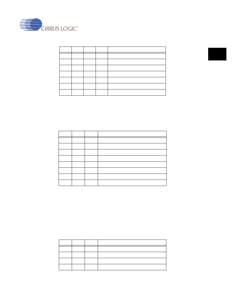
Shift - Read/Write
The Shift Mode is specified by selecting a value from
and writing it to this field.
P:
Pixel - Read/Write
The number of bits per pixel that are output on the P[x]
pins is specified by selecting a value from
and
writing it to this field.
The Graphics Engine has a separate setting for this value,
which may or may not be the same.
0
1
0
1
Blink to offset color single value mode
0
1
1
0
Blink to offset color 888 mode (555,565)
0
1
1
1
Undefined
1
1
0
0
Blink dimmer single value mode
1
1
0
1
Blink brighter single value mode
1
1
1
0
Blink dimmer 888 mode (555,565)
1
1
1
1
Blink brighter 888 mode (555,565)
Table 7-15. Output Shift Mode Table
S2
S1
S0
Shift Mode
0
0
0
1 - pixel per pixel clock (up to 24 bits wide)
0
0
1
1 - pixel mapped to 18 bits each pixel clock
0
1
0
2 - pixels per shift clock (up to 9 bits wide each)
0
1
1
4 - pixels per shift clock (up to 4 bits wide each)
1
0
0
8 - pixels per shift clock (up to 2 bits wide each)
1
0
1
2 2/3 3-bit pixels per clock over 8 bit bus
1
1
0
Dual Scan 2 2/3 3-bit pixels per clock over 8-bit bus
1
1
1
Undefined - Defaults to 1 - pixel per pixel clock
Table 7-16. Bits per Pixel Scanned Out
P2
P1
P0
Pixel Mode
0
0
0
pixel multiplexer disabled
0
0
1
4 bits per pixel
0
1
0
8 bits per pixel
0
1
1
do not use
Table 7-14. Blink Mode Definition Table (Continued)
M3
M2
M1
M0
Blink Mode