11 dma data transfer size determination, 1 software initiated m2m and m2p/p2m transfers, 11 dma data transfer size determination -17 – Cirrus Logic EP93xx User Manual
Page 411: 1 software initiated m2m and m2p/p2m transfers -17, Figure 10-4. edge-triggered dreq mode -17
DS785UM1
10-17
Copyright 2007 Cirrus Logic
DMA Controller
EP93xx User’s Guide
1
0
1
0
10
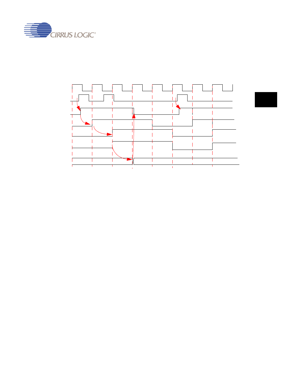
Subsequent changes on DREQ are ignored until the pending request begins to be
serviced. When the pending request has begun to be serviced, the DREQS status bit is
cleared and subsequent edge-triggered requests are again recognized (latched) by the
DMA. The DREQS status bit can be cleared by a software write to the channel STATUS
register, thus causing the DMA to ignore the request.
Figure 10-4. Edge-triggered DREQ Mode
1. A DREQ rising edge (DREQ is active high) is latched onto LATCH_DREQ during cycle
1.
2. This signal is synchronized using 2 HCLK flip-flops. The DREQS status bit indicates a
request is pending at start of cycle 3.
3. The DMA state machine moves into the DMA_MEM_RD state to begin servicing the first
request in cycle 4.
4. The DREQ latch is reset as a result of this state change and 2 cycles later the DREQS
status bit is cleared.
5. A second request cannot be recognized until DREQS is cleared. Hence the request
received during cycle 2 is ignored by the DMA.
6. A rising edge on DREQ during cycle 6 is latched and causes the DREQS status bit to be
set again, thus indicating that another external peripheral request is pending.
10.1.11 DMA Data Transfer Size Determination
10.1.11.1 Software Initiated M2M and M2P/P2M Transfers
Data transfer size flexibility is guaranteed by allowing the start address of a DMA transfer to
be aligned to any arbitrary byte boundary since this is the case for the 10 internal byte-wide
M2P/P2M channels and for the 2 M2M channels when used in software initiated mode.
HCLK
EXDREQ
LATCH_DREQ
DREQ_SYNC1
DREQ_SYNC2
DREQ
DMA_STATE
DMA_STALL
DMA_MEM_RD
1
2
3
4
5
6
7
8