4 pc card memory-mode enable signals, 5 pc card memory mapping, Table 12-3. supported 8-bit accesses -8 – Cirrus Logic EP93xx User Manual
Page 486: Table 12-4. supported 16-bit accesses -8, Table 12-5. pcmcia legacy usage -8
12-8
DS785UM1
Copyright 2007 Cirrus Logic
Static Memory Controller
EP93xx User’s Guide
1
2
1
2
12
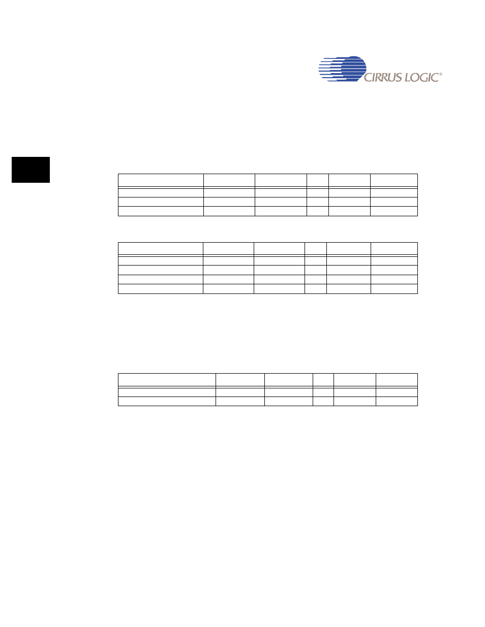
12.4 PC Card Memory-Mode Enable Signals
PC Card memory-mode enable signals, nPC_CE1 and nPC_CE2, are output on pin MCELn
and pin MCEHn, respectively. Along with the address signal output on pin AD[0] and the data
signals input or output on pins DA[15:8] and DA[7:0], the nPC_CE1 and nPC_CE2 signals
specify the type of access that is being made to the particular segment of memory in the PC
Card, as shown in
.
Note: Prior to version 8.0 of the PCMCIA specification, two valid types of odd-byte accesses to a
16-bit PC Card were defined as shown in
. The SMC does not support Type 1
odd-byte access to 16-bit PC Cards.
12.5 PC Card Memory Mapping
The address mapping for access to an 8- or 16-bit PC Card is shown in
, respectively.
Note: It is up to the programmer to provide an even address for all attribute memory access
operations (see PCMCIA Spec. 2.1), because the PCMCIA controller will generate the
physical address as shown in
and
, regardless of whether the least
significant address bit is 0b1 or 0b0.
Note: In
and
, bit 1 and bit 0 of the address each show a value of
0b1, 0b0, or 0bx. [25:2] refers to bit positions of the address, not address values.
Table 12-3. Supported 8-Bit Accesses
Access
nPC_CE2
nPC_CE1
A0
D15-D8
D7-D0
Stand by (no access)
1
1
X
Z
Z
Even Byte Access
0
0
0
Z
Even Byte
Odd Byte Access
1
0
1
Z
Odd Byte
Table 12-4. Supported 16-Bit Accesses
Access
nPC_CE2
nPC_CE1
A0
D15-D8
D7-D0
Stand by (no access)
1
1
X
Z
Z
Even Byte Access
1
0
0
Z
Even Byte
Odd Byte Access
1
0
1
Z
Odd Byte
Both Byte Access
0
0
Z
Odd Byte
Even Byte
Table 12-5. PCMCIA Legacy Usage
Access
nPC_CE2
nPC_CE1
A0
D15-D8
D7-D0
Type 1 - Odd-Byte Access
0
1
1
Odd-Byte
Z
Type 2 - Odd-Byte Access
1
0
1
Z
Odd-Byte