Table 10-7. ppalloc register reset values -24, Table 10-5, Table 10-6 – Cirrus Logic EP93xx User Manual
Page 418: Table 10-7
10-24
DS785UM1
Copyright 2007 Cirrus Logic
DMA Controller
EP93xx User’s Guide
1
0
1
0
10
NOTE: The naming convention used for channels and ports is as follows - even numbers
correspond to transmit channels/ports and odd numbers correspond to receive
channels/ports.
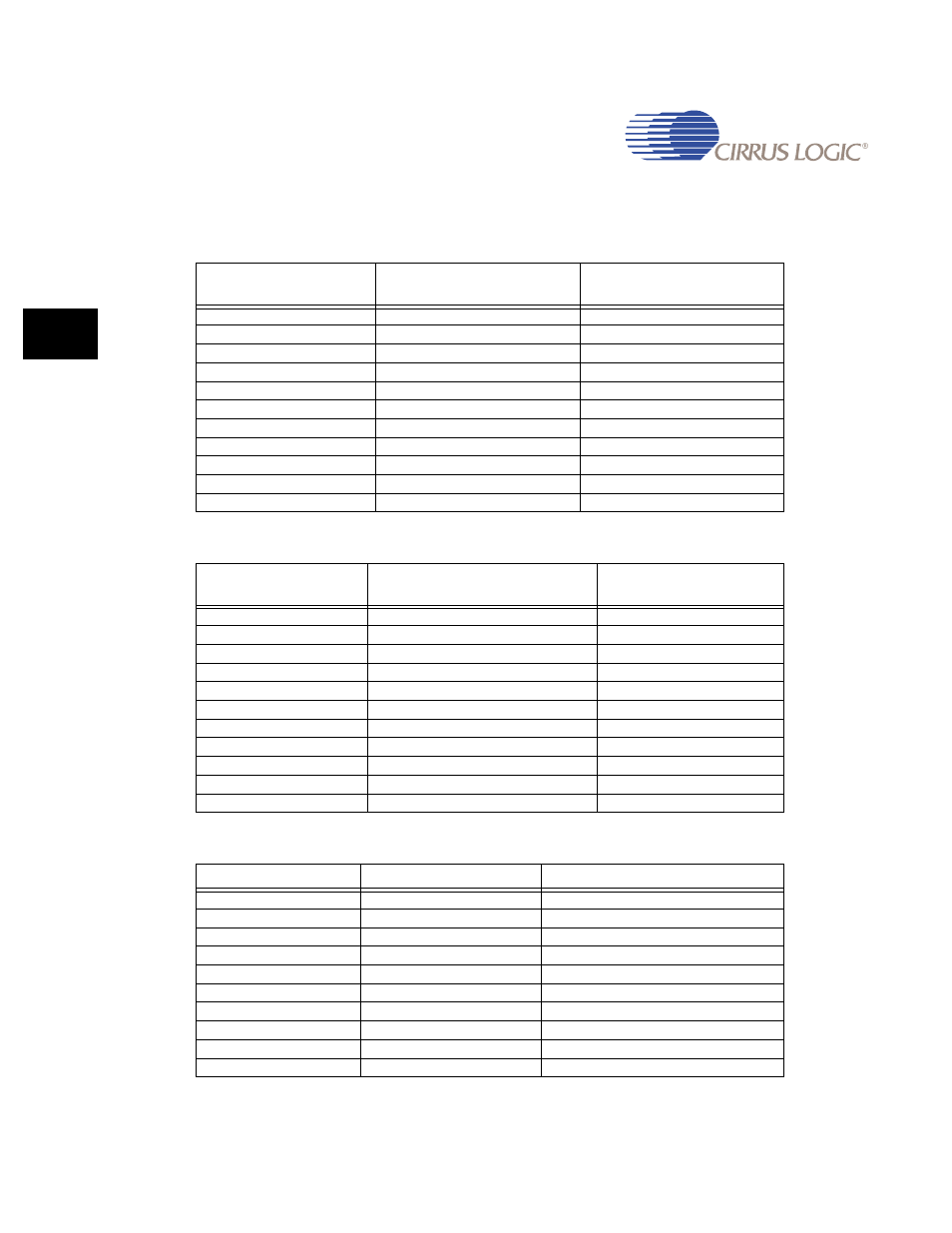
Table 10-5. PPALLOC Register Bits Decode for a Transmit Channel
Ch 0, 2, 4, 6, 8
PPALLOC[3:0]
Port allocated
Peripheral Allocated
0000
PORT 0
I2S1 Tx
0001
PORT 2
I2S2 Tx
0010
PORT 4
AAC1 Tx
0011
PORT 6
AAC2 Tx
0100
PORT 8
AAC3 Tx
0101
PORT 10
I2S3 Tx
0110
PORT 12
UART1 Tx
0111
PORT 14
UART2 Tx
1000
PORT 16
UART3 Tx
1001
PORT 18
IrDA Tx
other values
not used
Table 10-6. PPALLOC Register Bits Decode for a Receive Channel
Ch 1, 3, 5, 7, 9
PPALLOC[3:0]
Port allocated
Peripheral Allocated
0000
PORT 1
I2S1 Rx
0001
PORT 3
I2S2 Rx
0010
PORT 5
AAC1 Rx
0011
PORT 7
AAC2 Rx
0100
PORT 9
AAC3 Rx
0101
PORT 11
I2S3 Rx
0110
PORT 13
UART1 Rx
0111
PORT 15
UART2 Rx
1000
PORT 17
UART3 Rx
1001
PORT 19
IrDA Rx
other values
not used
Table 10-7. PPALLOC Register Reset Values
M2P Channel
PPALLOC[3:0]
Port allocated on reset
0
0000
PORT 0
1
0000
PORT 1
2
0001
PORT 2
3
0001
PORT 3
4
0010
PORT 4
5
0010
PORT 5
6
0011
PORT 6
7
0011
PORT 7
8
0100
PORT 8
9
0100
PORT 9