1 irda sir transmit encoder, 2 irda sir receive decoder, Figure 15-1 – Cirrus Logic EP93xx User Manual
Page 560
15-2
DS785UM1
Copyright 2007 Cirrus Logic
UART2
EP93xx User’s Guide
1
5
1
5
15
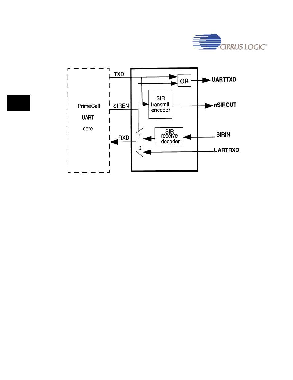
Figure 15-1. IrDA SIR Encoder/decoder Block Diagram
15.2.1.1 IrDA SIR Transmit Encoder
The SIR transmit encoder modulates the Non Return-to-Zero (NRZ) transmit bit stream
output from the UART. The IrDA SIR physical layer specifies use of a Return To Zero,
Inverted (RZI) modulation scheme which represents logic 0 as an infrared light pulse. The
modulated output pulse stream is transmitted to an external output driver and infrared Light
Emitting Diode (LED).
In normal mode, the transmitted pulse width is specified as three times the period of the
internal x16 clock (Baud16), that is, 3/16 of a bit period.
In low-power mode, the transmit pulse width is specified as 3/16 of a 115.2 Kbps bit period.
This is implemented as three times the period of a nominal 1.8432 MHz clock (IrLPBaud16)
derived by dividing down the UARTCLK clock. The frequency of IrLPBaud16 is set up by
writing the appropriate divisor value to UARTILPR. The active low encoder output is normally
LOW for the marking state (no light pulse). The encoder outputs a high pulse to generate a
infrared light pulse representing a logic “0” or spacing state.
15.2.1.2 IrDA SIR Receive Decoder
The SIR receive decoder demodulates the return-to-zero bit stream from the infrared detector
and outputs the received NRZ serial bit stream to the UART received data input. The decoder
input is normally HIGH (marking state) in the idle state (the transmit encoder output has the
opposite polarity to the decoder input).