Cirrus Logic EP93xx User Manual
Page 741
DS785UM1
25-3
Copyright 2007 Cirrus Logic
Analog Touch Screen Interface
EP93xx User’s Guide
2
5
2
5
25
For 8-wire touch screens, the SX and SY lines are used as the measurement reference for
the analog-to-digital converter to provide better resolution during a reading and compensate
for any drift in samples due to other factors. A 4-wire analog resistive touch screen is the
same as an 8-wire without the SX and SY feedback lines. A 4-wire analog resistive touch
screen may be adequate for non-industrial use or small touch screens.
For 5-wire touch screens and 7-wire (5-wires with feedback) touch screens, a constant
voltage is applied from corner to corner of the lower layer. Switching of the X and Y axis is
performed by driving appropriate voltages on Z+/- and Z-/+. The location values during both
the X and Y scans are then read by sampling the Wiper input. A 7-wire touch screen (5-wires
with feedback), provides reference feedback voltages to the analog-to-digital converter to
eliminate analog switch and other circuit resistances.
The changes in connection for sampling are performed by a set of separately controlled
analog switches. These switches may be connected in a variety of ways which allows a high
degree of flexibility in using the analog-to-digital converter. To avoid contention, each switch
drive circuit has a much faster turn-off than turn-on to provide an overall break-before-make
array function.
Logic safeguards are included to condition the control signals for power connection to the
matrix to prevent part damage. In addition, a software lock register is included that must be
written with 0xAA before each register write to change the values of the four switch matrix
control registers.
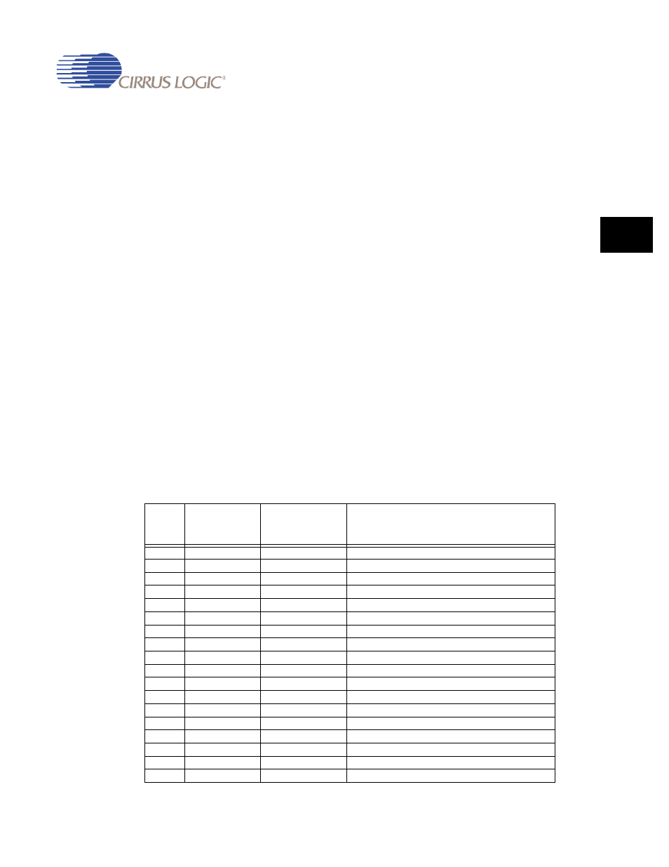
provides switch definitions and the logical safeguards that are implemented to
prevent physical part damage. A “1” in the register bit position closes the corresponding
switch.
Table 25-1. Switch Definitions and Logical Safeguards to Prevent Physical Damage
Switc
h
CTL
Connection
From
Connection
To
Only allowed if
Bit 0
X+
ADC input
-
Bit 1
X-
ADC input
-
Bit 2
Y+
ADC input
-
Bit 3
Y-
ADC input
-
Bit 4
sY-
ADC input
-
Bit 5
sY+
ADC input
-
Bit 6
sX-
ADC input
-
Bit 7
sX+
ADC input
-
Bit 8
VBAT
ADC input
SW8 = HIGH and the bus SW[7-0] = 0x00
Bit 9
AVDD
ADC REF+
SW9 = HIGH and SW26 = LOW and SW24 = LOW
Bit 10
AGND
ADC REF-
-
Bit 11
X+
AGND
-
Bit 12
X-
AGND
-
Bit 13
Y+
AGND
-
Bit 14
Y-
AGND
-
Bit 15
sX+
AGND
-
Bit 16
sX-
AGND
-
Bit 17
sY+
AGND
-