5 usb host controller blocks, 1 ahb slave, 2 ahb master – Cirrus Logic EP93xx User Manual
Page 449: 3 hci slave block, 5 usb host controller blocks -9, Figure 11-6. usb host controller block diagram -9, Figure 11-6
DS785UM1
11-9
Copyright 2007 Cirrus Logic
Universal Serial Bus Host Controller
EP93xx User’s Guide
1
1
1
1
11
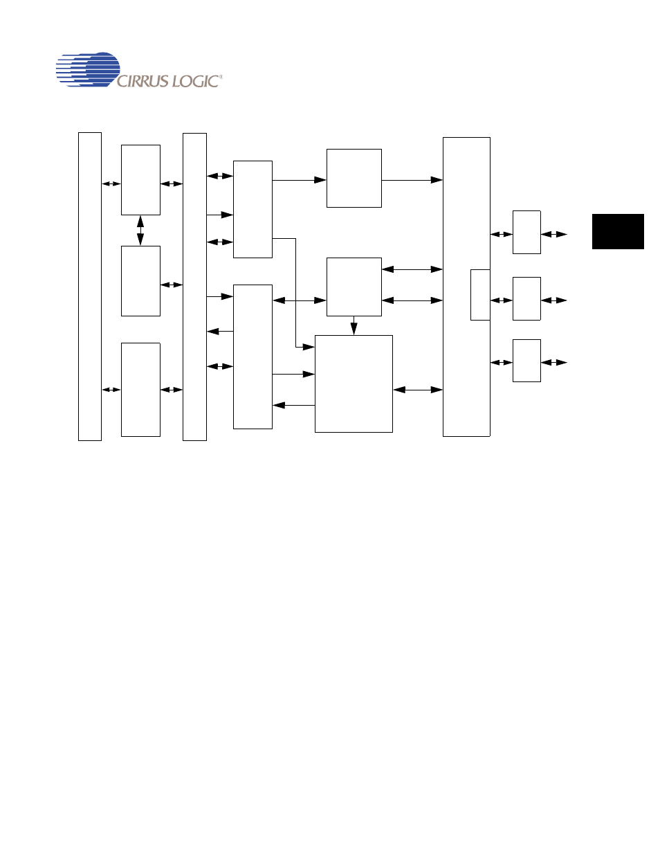
Figure 11-6. USB Host Controller Block Diagram
11.2.5 USB Host Controller Blocks
11.2.5.1 AHB Slave
This block allows access to the OHCI operational registers from/to the AHB via the HCI Bus.
11.2.5.2 AHB Master
This block enables the USB Host Controller to be an AHB Master peripheral and interfaces
with the HCI Master block via the HCI Bus.
The AHB Master includes a Data FIFO which will use a 44x37 bit Data FIFO. 32-bit data, 4-bit
HCI_MBeN[3:0] (byte lane enables) and HCI_MWBstOnN (burst on) make up the width of the
Data FIFO.
11.2.5.3 HCI Slave Block
This block contains the OHCI operational registers, which are programmed by the Host
Controller Driver (HCD).
A
H
B
H
C
I
B
U
S
AHB
Slave
AHB
Master
HCI
Slave
HCI
Master
USB State
Control
Data FIFO
64x8
List Processor
(including End
Descriptor and
Transfer
Descriptor
registers)
Root
Hub &
Host SIE
P
L
L
XVR
XVR
1
3
USB
USB
Control
Control
Control
Control
Control
Cntr
l
Cntrl
Addr
Data
Data
Addr/
Data
Data
ED/TD
Data
ED/TD
Status
Data
Status
XVR
USB
USB
Host
Test
Reg
2