Table 13-1. boot device selection -2, Table caution – Cirrus Logic EP93xx User Manual
Page 498
13-2
DS785UM1
Copyright 2007 Cirrus Logic
SDRAM, SyncROM, and SyncFLASH Controller
EP93xx User’s Guide
1
3
1
3
13
Length = 0x4 (32-bit wide memory bus) or Burst Length = 0x8 (16-bit wide memory bus) to
the Mode register that is inside the SyncROM device.
For a Synchronous FLASH device, the configuration sequence writes RAS = 0x2 and CAS =
0x5 to the SDRAMDevCfg[3:0] register and writes WBM = 0x0, CAS = 0x3, and either Burst
Length = 0x4 (32-bit wide memory bus) or Burst Length = 0x8 (16-bit wide memory bus) to
the Configuration register that is inside the SyncFLASH device.
CAUTION: Do not attempt to configure the registers of other synchronous memory
banks while booting from Synchronous Memory Bank 3. Attempting to do so may
cause the system to lock-up. Rather, it is advised that the boot code copy the
configuration code for other synchronous memory banks to some non-synchronous
memory space, and then later configure the registers of the other synchronous
memory banks from that space.
The power-up sequence that is executed when the power-on reset becomes asserted is:
1. The SDCLKEN and DQM[3:0] pins are each externally pulled high so that they rise with
the VDD and VDDQ power supplies.
2. Following power-up, the ARM Core is held in the reset state with HCLK running. The
CKE bit in the Global configuration register, GlConfig, is written to ‘1’ to enable HCLK to
be output on the SDCLK pin. Initialize = ‘1’, MRS = ‘1’, and LCR = ‘0’, shown in
,
are written to the GlConfig register to cause a NOP access to be issued. Continuous
NOP accesses are issued for 200
μ
s.
3. Initialize = ‘0’, MRS = ‘1’, and LCR = ‘0’ are written to the GlConfig register to enable
access to the Mode register that is inside the synchronous memory device. Default
settings are then written to the Mode register by reading the appropriate address, where
the value of the address itself is the value of the default setting. For a Synchronous
ROM device, the default settings are RAS = 0x2, CAS = 0x5, and either Burst Length =
0x4 (32-bit wide memory bus) or Burst Length = 0x8 (16-bit wide memory bus). For a
Synchronous FLASH device, the default settings are WBM = 0x0, CAS = 0x3, and either
Burst Length = 0x4 (32-bit wide memory bus) or Burst Length = 0x8 (16-bit wide
memory bus).
4. Three SDCLK cycles after the Mode register is written with the appropriate default value,
the memory portion of the synchronous memory device is ready for power-up with all of
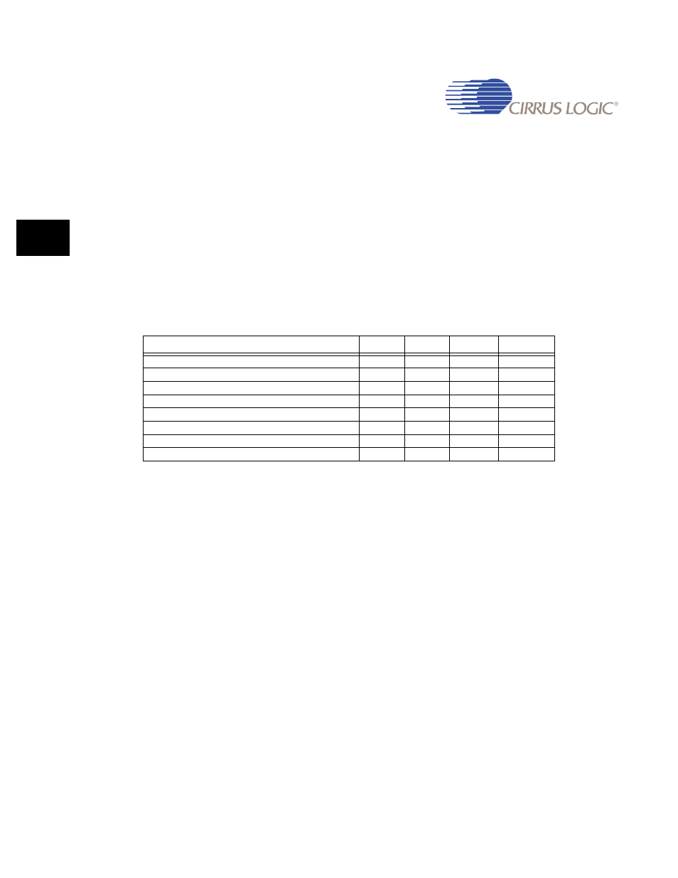
Table 13-1. Boot Device Selection
Boot modes
CSn7
CSn6
ASDO
EECLK
8-bit ROM
0
0
0
0
16-bit ROM
0
1
0
0
32-bit ROM
1
0
0
0
32-bit ROM
1
1
0
0
16-bit SFLASH (Initializes Command Register)
0
0
1
0
16-bit SROM (Initializes Mode Register)
0
1
1
0
32-bit SFLASH (Initializes Command Register
1
0
1
0
32-bit SROM (Initializes Mode Register)
1
1
1
0