Cirrus Logic EP93xx User Manual
Page 581
DS785UM1
16-5
Copyright 2007 Cirrus Logic
UART3 With HDLC Encoder
EP93xx User’s Guide
1
6
1
6
16
BE:
Break Error. This bit is set to 1 if a break condition was
detected, indicating that the received data input was held
LOW for longer than a full-word transmission time (defined
as start, data, parity and stop bits). This bit is cleared to 0
after a write to UART3RXSts. In FIFO mode, this error is
associated with the character at the top of the FIFO. When
a break occurs, only one 0 character is loaded into the
FIFO. The next character is only enabled after the receive
data input goes to a 1 (marking state) and the next valid
start bit is received.
PE:
Parity Error. When this bit is set to 1, it indicates that the
parity of the received data character does not match the
parity selected in UART3LinCtrlHigh (bit 2). This bit is
cleared to 0 by a write to UART3RXSts. In FIFO mode,
this error is associated with the character at the top of the
FIFO.
FE:
Framing Error. When this bit is set to 1, it indicates that the
received character did not have a valid stop bit (a valid
stop bit is 1). This bit is cleared to 0 by a write to
UART3RXSts. In FIFO mode, this error is associated with
the character at the top of the FIFO.
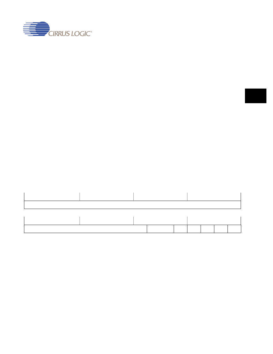
UART3LinCtrlHigh
Address:
0x808E_0008 - Read/Write
Default:
0x0000_0000
Definition:
UART3 Line Control Register High. UART3LinCtrlHigh, UART3LinCtrlMid and
UART3LinCtrlLow form a single 23-bit wide register (UART3LinCtrl) which is
updated on a single write strobe generated by an UART3LinCtrlHigh write. So,
in order to internally update the contents of UART3LinCtrlMid or
UARTBLCR_L, a UART3LinCtrlHigh write must always be performed at the
end.
To update the three registers there are two possible sequences:
• UART3LinCtrlLow write, UART3LinCtrlMid write and UART3LinCtrlHigh write
31
30
29
28
27
26
25
24
23
22
21
20
19
18
17
16
RSVD
15
14
13
12
11
10
9
8
7
6
5
4
3
2
1
0
RSVD
WLEN
FEN
STP2
EPS
PEN
BRK