6 motorola® spi frame format, 1 spo clock polarity, 2 sph clock phase – Cirrus Logic EP93xx User Manual
Page 717: 7 motorola spi format with spo=0, sph=0, 6 motorola, 7 motorola spi format with spo=0, sph=0 -5
DS785UM1
23-5
Copyright 2007 Cirrus Logic
Synchronous Serial Port
EP93xx User’s Guide
2
3
2
3
23
23.5.6 Motorola
®
SPI Frame Format
The Motorola SPI interface is a four-wire interface where the SFRMOUT signal behaves as a
slave select. The main feature of the Motorola SPI format is that the inactive state and phase
of the SCLKOUT signal are programmable through the SPO and SPH bits within the control
register,
23.5.6.1 SPO Clock Polarity
When the SPO clock polarity control bit is LOW, it produces a steady state low value on the
SCLKOUT pin. If the SPO clock polarity control bit is HIGH, a steady state high value is
placed on the SCLKOUT pin when data is not being transferred.
23.5.6.2 SPH Clock Phase
The SPH control bit selects the clock edge that captures data and allows it to change state. It
has the most impact on the first bit transmitted by either allowing or not allowing a clock
transition before the first data capture edge.
When the SPH phase control bit is LOW, data is captured on the first clock edge transition. If
the SPH clock phase control bit is HIGH, data is captured on the second clock edge
transition.
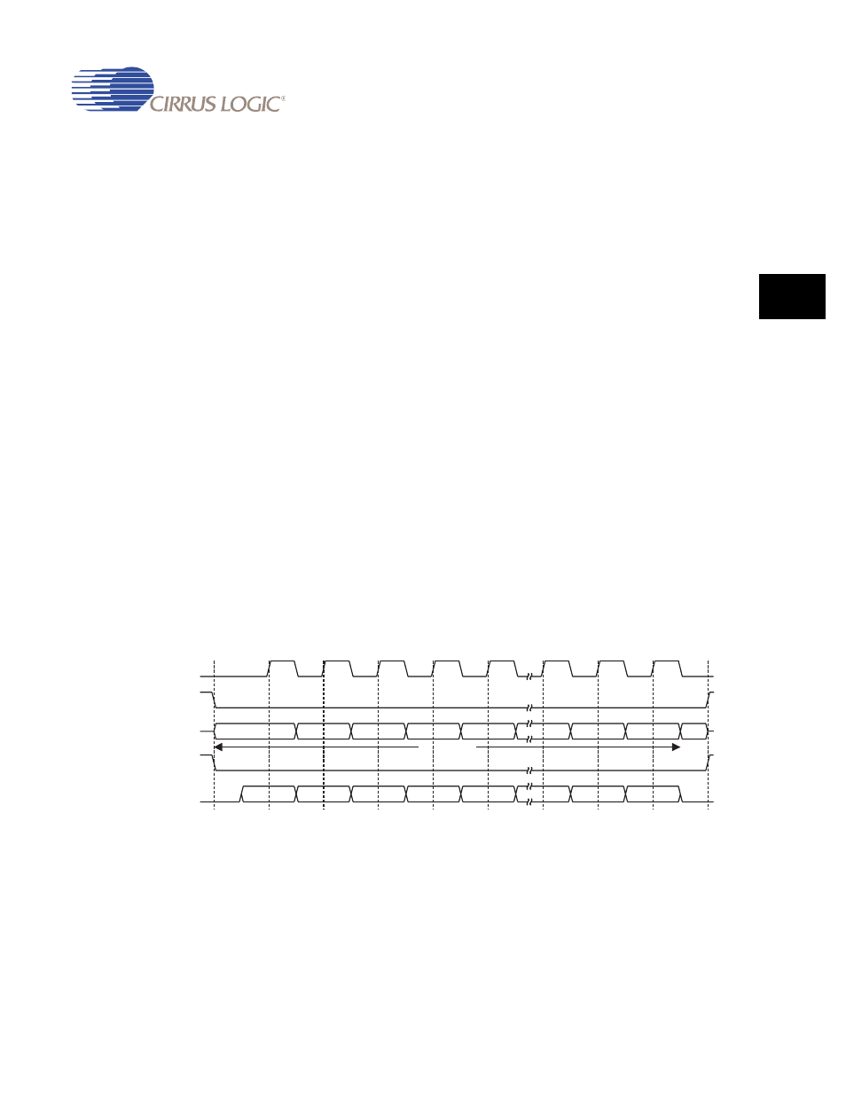
23.5.7 Motorola SPI Format with SPO=0, SPH=0
Single and continuous transmission signal sequences for Motorola SPI format with SPO=0,
SPH=0 are shown in
.
Figure 23-3. Motorola SPI Frame Format (Single Transfer) with SPO=0 and SPH=0
4 to 16 bits
MS B
LS B
Q
LS B
MS B
SSPTXD
SSPOE
SSPRXD
SFRMOUT /
SFRMIN
SCLKOUT /
SCLKIN