1 clocking requirements, 1 clocking requirements -15, Table 14-4. uart1 pin functionality -15 – Cirrus Logic EP93xx User Manual
Page 537: Table 14-5. devicecfg register bit functions -15
DS785UM1
14-15
Copyright 2007 Cirrus Logic
UART1 With HDLC and Modem Control Signals
EP93xx User’s Guide
1
4
1
4
14
The use of EGPIO[3] is determined by several bits in Syscon register DeviceCfg. See
.
14.5.1 Clocking Requirements
There are two clocks, PCLK and UARTCLK.
UARTCLK frequency must accommodate the desired range of baud rates:
The frequency of UARTCLK must also be within the required error limits for all baud rates to
be used.
To allow sufficient time to write the received data to the receive FIFO, UARTCLK must be less
than or equal to four times the frequency of PCLK:
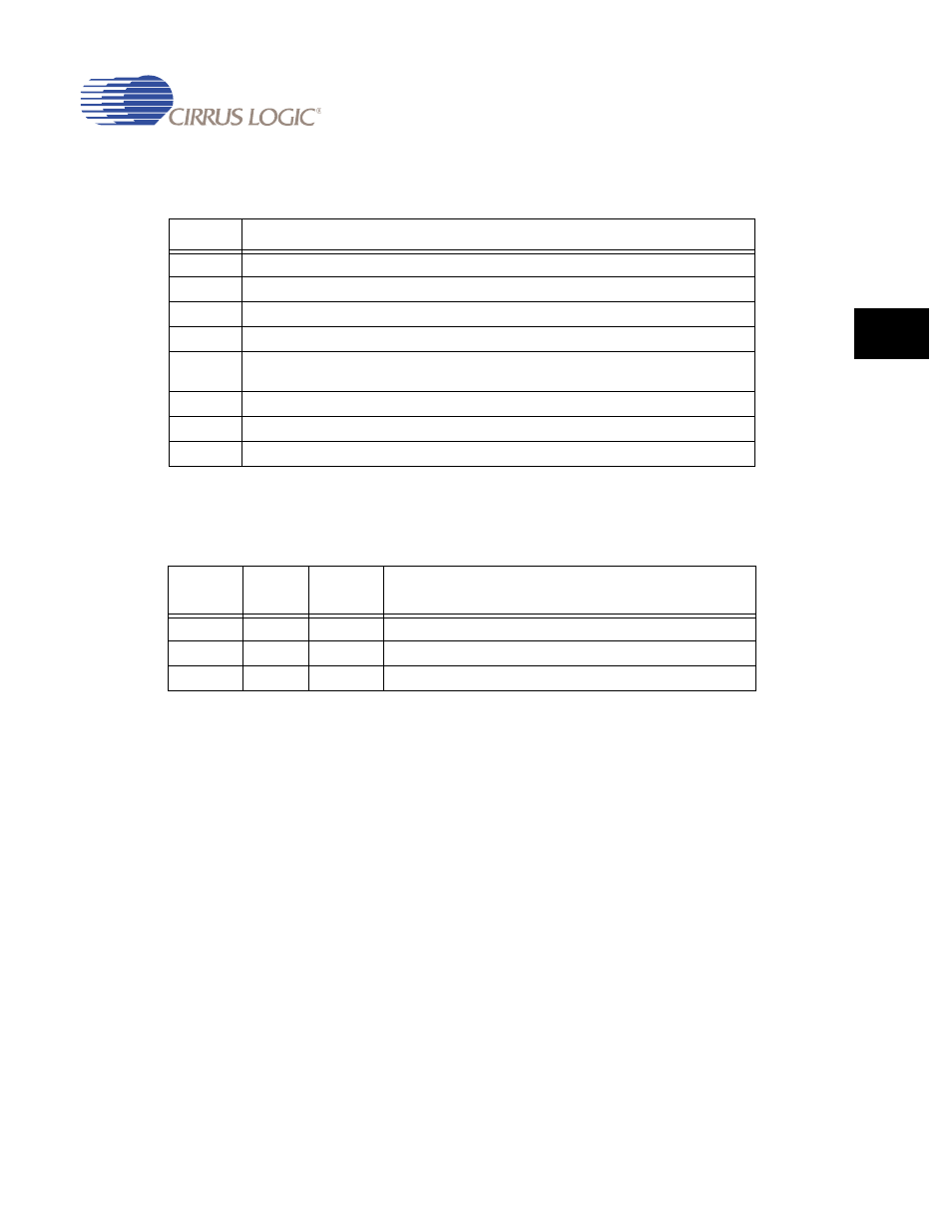
Table 14-4. UART1 Pin Functionality
PIN
Description
RXD0
UART1 input pin
TXD0
UART1 output pin
CTSn
Modem input: Clear To Send
DSRn
Modem input: Data Set Ready (also used for DCDn Data Carrier Detect)
EGPIO[0]
Modem input RIn: Ring Indicator if Syscon register DeviceCfg[25] MODonGPIO is set.
Otherwise, RIn is driven low.
DTRn
Modem output Data Terminal Ready if Syscon register TESTCR[27] RTConGPIO is clear.
RTSn
Modem output: Ready To Send
EGPIO[3]
HDLC clock
Table 14-5. DeviceCfg Register Bit Functions
bit 14
HC3EN
bit 13
HC1IN
bit 12
HC1EN
Function
x
0
x
External HDLC clock input is driven low.
0
1
1
External HDLC clock input is driven by EGPIO[3].
0
0
1
Internal HDLC clock output drives EGPIO[3].
F
UARTCLK
MIN
32
baudrate
MAX
×
≥
F
UARTCLK
MA X
32
65536
b
×
audrate
MIN
×
≤
F
UARTCLK
4
F
PCLK
Ч
≤