Keypad interface, 1 introduction, Chapter 26. keypad interface -1 – Cirrus Logic EP93xx User Manual
Page 763: 1 introduction -1, Figure 26-1. key array block diagram -1, Chapter 26, Chapter 26 26 keypad interface
DS785UM1
26-1
Copyright 2007 Cirrus Logic
2
6
2
6
26
Chapter 26
26
Keypad Interface
26.1 Introduction
Note: This chapter applies only to the EP9307, EP9312, and EP9315 processors.
The keypad interface has the following features:
•
A maximum 8x8 array of normally open, single pole contacts
•
A back drive feature to minimize capacitance effects
•
A typical scan count limit of 3 consecutive scans
•
A maximum mechanical bounce time for a key press of 20 milliseconds
•
A typical interrupt interval between 24 and 44 milliseconds
•
A low-power wakeup mode
•
A three-key reset
If the system does not use a keyboard, the Row[7:0] and Column[7:0] pins can be remapped
to General Purpose Input/Output (GPIO) pins. For details, see
,
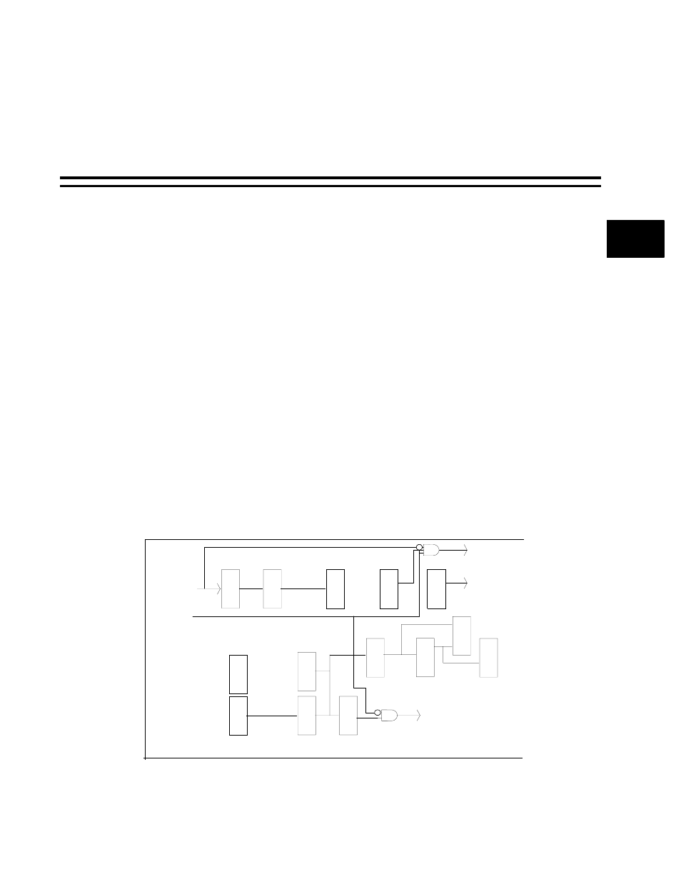
A block diagram for the key array scanning circuitry is shown in
.
Figure 26-1. Key Array Block Diagram
Precounter
Debounce Counter
Row/Collumn
Counter
Pipeline
Scan
Control
Row Decoder
Column Mux
Temp Key Regs
Key Regs
Interrupt
Controller
3 Key Reset Key Detector
Diagnostics
Equal
Compare
Pipeline
Row lines
Column lines
Inactive
Interrrupt
3 Key Reset