Y to pll2 and the, Clkset2 – Cirrus Logic EP93xx User Manual
Page 146
5-20
DS785UM1
Copyright 2007 Cirrus Logic
System Controller
EP93xx User’s Guide
5
5
5
nBYP1:
This bit selects the clock source for the processor clock
dividers. With this bit clear, the system wakes up and
boots with the PLL bypassed and uses an external clock
source. With nBYP1 set, the system runs with the PLL
generated clock. The default for this bit is to boot/run from
external clock source.
SMCROM:
If set, this bit will gate off the HCLK to the Static Memory
Controller when in Halt mode and therefore save power.
When in Halt mode, there are no Instruction Code fetches
occurring and therefore if there are no DMA operations in
progress that may require the SMC, there will be no
accesses to this controller. It may therefore be safely
disabled when in Halt mode. This bit is 0b on reset.
FCLKDIV:
These three bits set the divide ratio between the VCO
output and processor clock. On power-on-reset the value
is set to 000b.
000 - Divide by 1 011 - Divide by 8
001 - Divide by 2 100 - Divide by 16
010 - Divide by 4
For FCLKDIV values equal to 1xxb (except for 100b), the
divide ratio will be divide by 1.
ClkSet2
Address:
0x8093_0024 - Read/Write
Definition:
The ClkSet2 register is used for setting the dividers internally to PLL2 and to
the USB Host divider. The reset setting for PLL2 creates a frequency of
48 MHz. The default divider for USB_DIV is divide by 1, which will produce the
USB host clock frequency and FIR clock frequency of 48 MHz.
Bit Descriptions:
PLL2_X2IPD:
These 5 register bits set the input divider for PLL2
operation. On power-on-reset the value is set to 10111b
(23 decimal).
Note: The value in the register is the actual coefficient minus one.
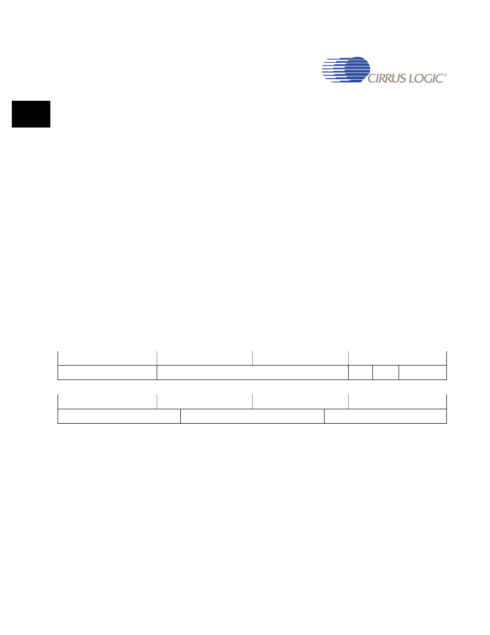
31
30
29
28
27
26
25
24
23
22
21
20
19
18
17
16
USB DIV
RSVD
nBYP2
PLL2_EN
PLL2_PS
15
14
13
12
11
10
9
8
7
6
5
4
3
2
1
0
PLL2 X1FBD1
PLL2 X2FBD2
PLL2 X2IPD