Figure 1-2. ep9302 block diagram -3, Figure 1-3. ep9307 block diagram -3, Figure 1-2 – Cirrus Logic EP93xx User Manual
Page 31: Figure 1-3
DS785UM1
1-3
Copyright 2007 Cirrus Logic
Introduction
EP93xx User’s Guide
1
1
1
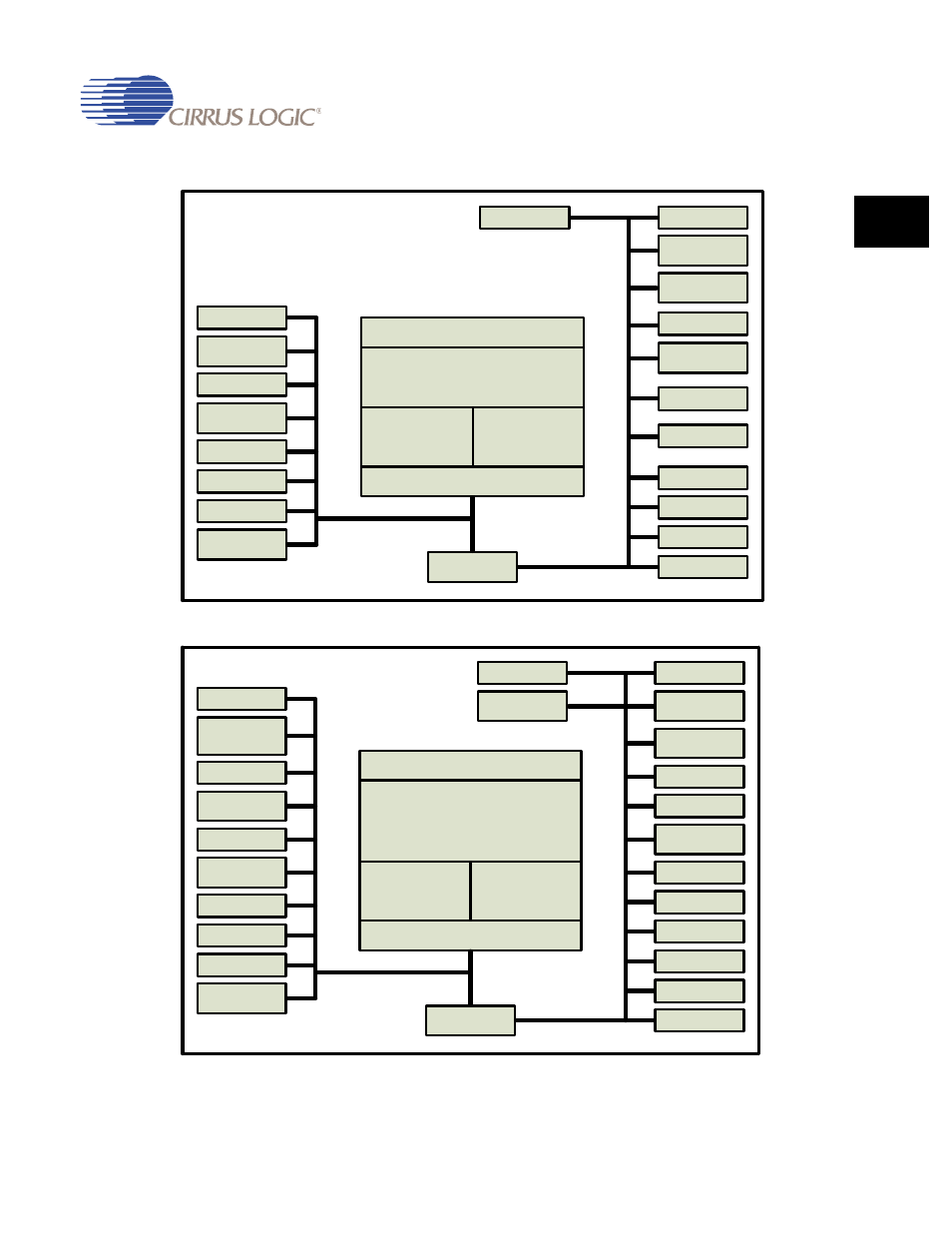
Figure 1-2. EP9302 Block Diagram
Figure 1-3. EP9307 Block Diagram
5-Channel ADC
2 PWMs
Enhanced GPIO,
2-wire, 2 LED
I
2
S
SPI
AC’97
RTC with SW Trim
Watchdog Timer
4 Timers
System Control –
2 PLLs
UART1 with HDLC
SDRAM
SRAM, FLASH,
ROM
12 Channel DMA
1/10/100 Ethernet
MAC
JTAG
2 USB 2.0 FS Host
Boot ROM
UART2 with IrDA
ARM920T
I-Cache
16 KB
D-Cache
16 KB
Memory Management Unit
AHB/APB Bridge
Vectored
Inerrupts
High-Speed Bus (AHB)
Peripheral Bus (APB)
MaverickCrunch
TM
Coprocessor
8-Wire
Touchscreen ADC
8x8 Matrix Keypad
1 PWM
Enhanced GPIO
EEPROM, 2 LED
I
2
S
SPI
AC’97
RTC with SW Trim
Watchdog Timer
4 Timers
System Control –
2 PLLs
UART1 with HDLC
18-bit Raster LCD
plus CCITT656
Video
SDRAM
SRAM, FLASH,
ROM
12 Channel DMA
1/10/100 Ethernet
MAC
JTAG
3 USB 2.0 FS Host
Boot ROM
UART2 with IrDA
UART3 with HDLC
ARM920T
I-Cache
16 KB
D-Cache
16 KB
Memory Management Unit
AHB/APB Bridge
Vectored
Inerrupts
High-Speed Bus (AHB)
Peripheral Bus (APB)
MaverickCrunch
TM
Coprocessor
2D Graphics