2 frame format, 2 frame format -9, Figure 17-1. rz1/nrz bit encoding example -9 – Cirrus Logic EP93xx User Manual
Page 605: Table 17-3. mir frame format -9
DS785UM1
17-9
Copyright 2007 Cirrus Logic
IrDA
EP93xx User’s Guide
1
7
1
7
17
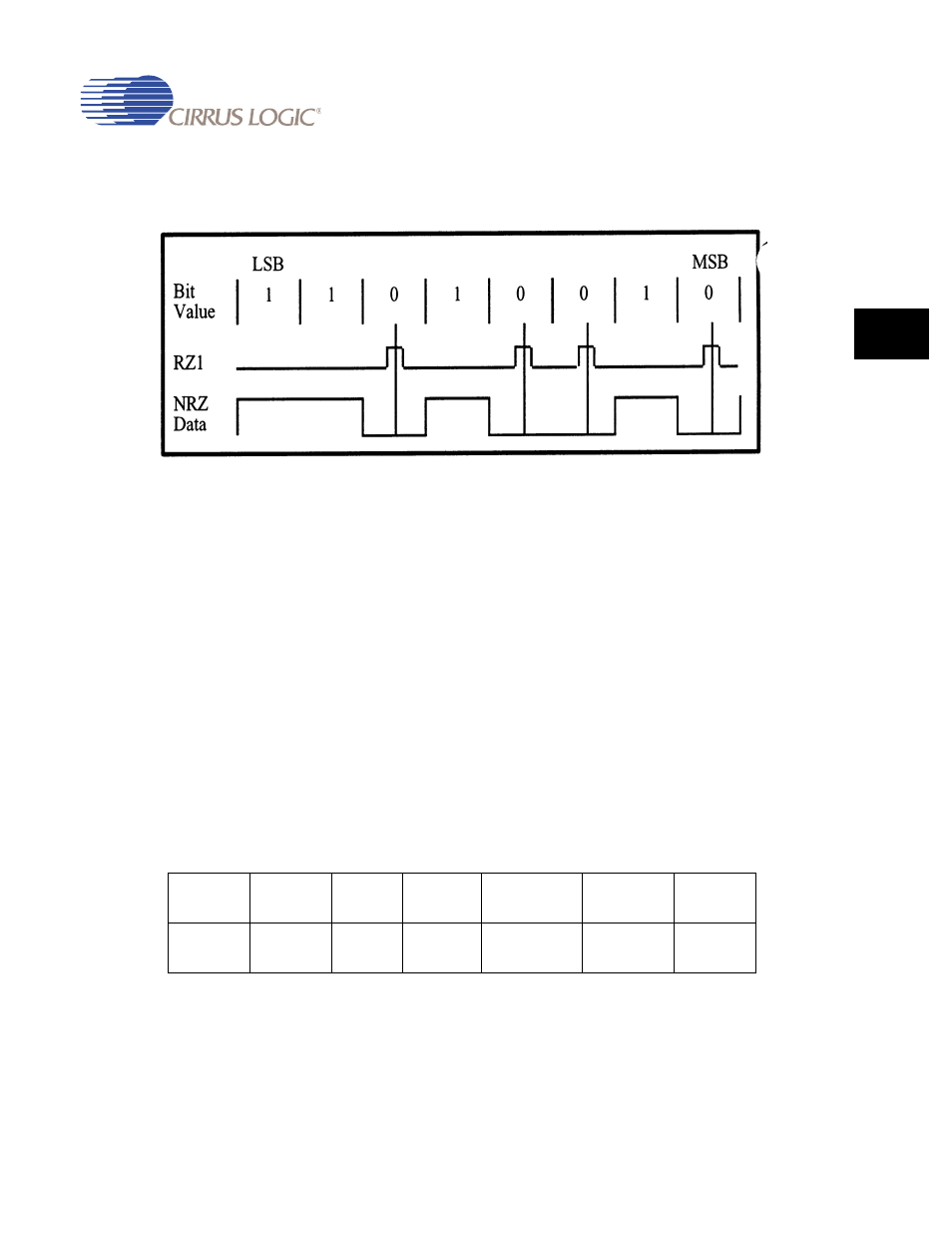
Figure 17-1. RZ1/NRZ Bit Encoding Example
17.4.1.2 Frame Format
MIR uses a flag (reserved bit pattern) to denote the beginning and end of a frame of
information and to synchronize frame transmission. A double flag is used to indicate the start
of a frame and a single flag the end. The flag contains eight bits, which start and end with a
zero and contain six sequential ones in the middle (01111110b). This sequence of six ones is
unique because all data between the start and stop flag is prohibited from having more than
five consecutive ones. Data that violates this rule is altered before transmission by
automatically inserting a zero after five consecutive ones are detected in the transmitted bit
stream. This technique is commonly referred to as “bit stuffing” and is transparent to the user.
The information field within a MIR frame is placed between the start and stop flags, consisting
of an 8 bit address, an optional 8 bit control field, a data field containing any multiple of 8 bits
and a 16 bit cyclic redundancy check (CRC-CCITT). Note that each byte within the address,
control and data fields is transmitted and received LSB first, ending with the byte’s MSB.
However, the CRC is transmitted and received MSB first. The MIR frame format is outlined
below in
Table 17-3. MIR Frame Format
8 Bits
8 Bits
8 Bits
8 Bits
(optional)
Any multiple
of 8 Bits
16 Bits
8 Bits
Start Flag
0111 1110
Start Flag
0111 1110
Address
Control
Data
CRC-CCITT
Stop Flag
0111 1110