Cirrus Logic EP93xx User Manual
Page 584
16-8
DS785UM1
Copyright 2007 Cirrus Logic
UART3 With HDLC Encoder
EP93xx User’s Guide
1
6
1
6
16
BR:
Baud Rate Divisor bits [7:0]. Least significant byte of baud
rate divisor. These bits are cleared to 0 on reset. The baud
rate divisor is calculated as follows:
Baud rate divisor BAUDDIV = (F
UARTCLK
/ (16 * Baud
rate)) –1
where F
UARTCLK
is the UART reference clock frequency. A
baud rate divisor of zero is not allowed and will result in no
data transfer.
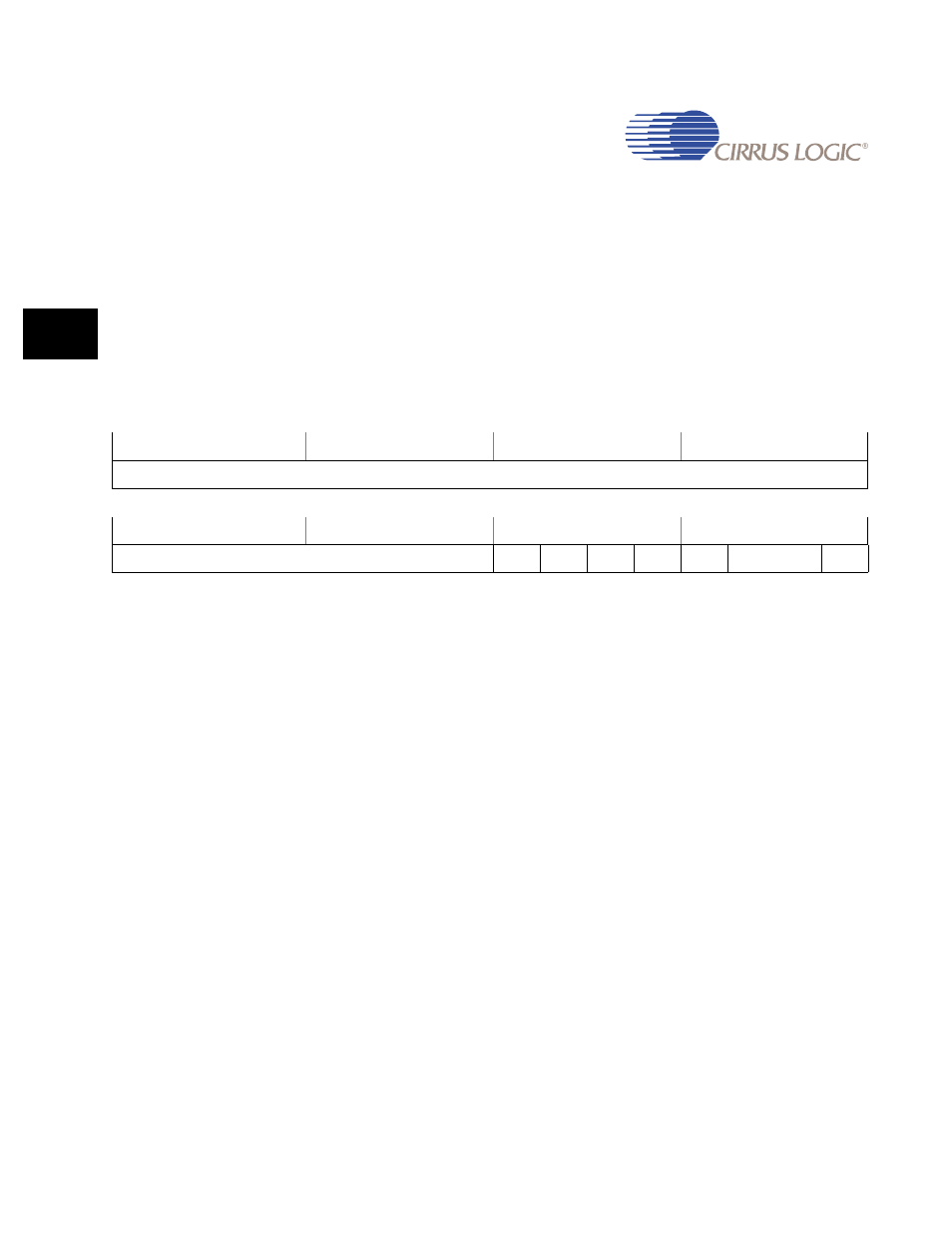
UART3Ctrl
Address:
0x808E_0014 - Read/Write
Default:
0x0000_0000
Definition:
UART3 Control Register
Bit Descriptions:
RSVD:
Reserved. Unknown During Read.
LBE:
Loopback Enable. If this bit is set to 1, data sent to TXD is
received on RXD. This bit is cleared to 0 on reset, which
disables the loopback mode.
RTIE:
Receive Timeout Enable. If this bit is set to 1, the receive
timeout interrupt is enabled.
TIE:
Transmit Interrupt Enable. If this bit is set to 1, the transmit
interrupt is enabled.
RIE:
Receive Interrupt Enable. If this bit is set to 1, the receive
interrupt is enabled.
MSIE:
Modem Status Interrupt Enable. If this bit is set to 1, the
modem status interrupt is enabled.
UARTE:
UART Enable. If this bit is set to 1, the UART is enabled.
Data transmission and reception occurs for UART signals.
31
30
29
28
27
26
25
24
23
22
21
20
19
18
17
16
RSVD
15
14
13
12
11
10
9
8
7
6
5
4
3
2
1
0
RSVD
LBE
RTIE
TIE
RIE
MSIE
RSVD
UARTE