Cursorxyloc, Regi – Cirrus Logic EP93xx User Manual
Page 252
7-70
DS785UM1
Copyright 2007 Cirrus Logic
Raster Engine With Analog/LCD Integrated Timing and Interface
EP93xx User’s Guide
7
7
7
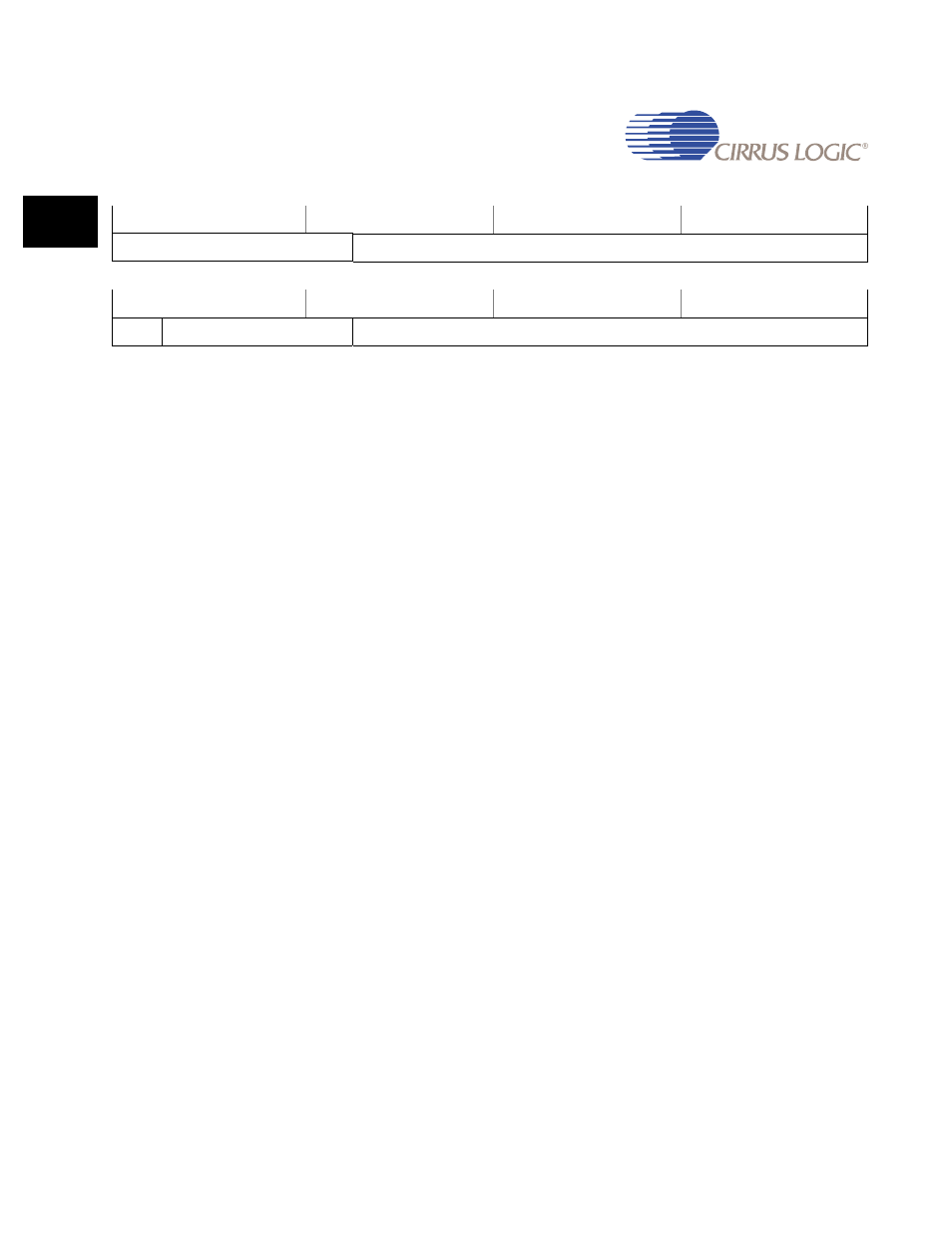
CursorXYLoc
Address: 0x8003_0074
Default: 0x0000_0000
Definition: Cursor X and Y Location register
Bit Descriptions:
RSVD:
Reserved - Unknown during read
YLOC:
Y Location - Read/Write
The Y Location value written to this field specifies the
starting vertical Y location of the cursor image. The value
is compared to the vertical line counter and it should be
specified to be between the active start and active stop
vertical line values.
The cursor hardware will clip the cursor at the bottom of
the screen. To prevent cursor distortion, a new Y Location
value will not be used until the next frame.
CEN:
Cursor Enable - Read/Write
Writing a ‘1’ to this bit enables the hardware to insert the
defined cursor into the image output video stream. The
cursor image fetched from an SDRAM location that is
defined by the
the output video stream. Writing a ‘0’ to this bit disables
the cursor.
0 - Hardware cursor not enabled
1 - Hardware cursor enabled
When Dual Scan mode is enabled by writing DSCAN = ‘1’
in the
register, this Cursor Enable bit specifies
that some or all of the cursor is located in the upper half of
the display.
XLOC:
Y Location - Read/Write
31
30
29
28
27
26
25
24
23
22
21
20
19
18
17
16
RSVD
YLOC
15
14
13
12
11
10
9
8
7
6
5
4
3
2
1
0
CEN
RSVD
XLOC