Ac’97 controller, 1 introduction, Chapter 22. ac’97 controller -1 – Cirrus Logic EP93xx User Manual
Page 689: 1 introduction -1, Table 22-1. ac’97 input and output signals -1, Chapter 22
DS785UM1
22-1
Copyright 2007 Cirrus Logic
2
2
2
2
22
Chapter 22
22
AC’97 Controller
22.1 Introduction
The AC’97 Controller includes a 5-pin serial interface to an external audio codec. The AC-
Link is a bi-directional, fixed rate, serial PCM (Pulse Code Modulation) digital stream, dividing
each audio frame into 12 outgoing and 12 incoming data streams (slots), each with 20-bit
sample resolution.
The AC’97 Controller contains logic that controls the AC-Link to the audio codec and an
interface to the AMBA APB.
The main features of the AC’97 are:
•
Serial-to-parallel conversion on data received from the external codec.
•
Parallel-to-serial conversion on data transmitted to the external codec.
•
Reception / Transmission of control and status information.
•
Supports up to 4 different sampling rates at a time with 4 transmit and 4 receive
channels. The transmit and receive paths are buffered with internal FIFO memories
allowing data to be stored independently in both transmit and receive modes. The data
for the FIFOs can be written via either the APB interface or the DMA channels (1-3).
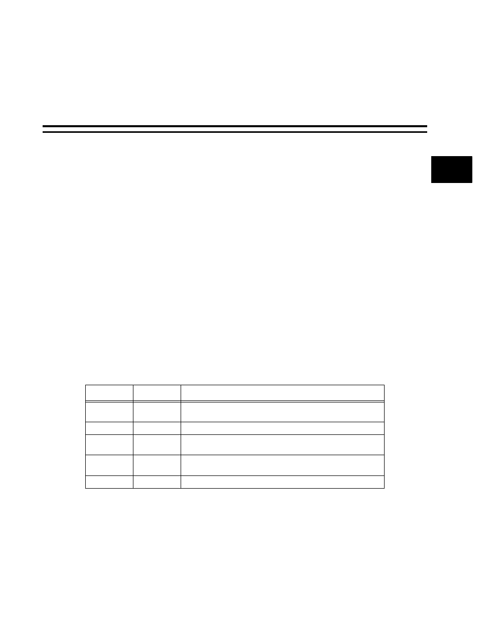
lists the input and output signals for the AC’97 controller.
The AC’97 pins are multiplexed and may be used for the I
2
S controller instead of AC'97 by
setting DeviceCfg.I2SonAC97.
The AC’97 Controller can support up to four different sampling rates at a time. To allow the
controller to support all slots per frame, it has been assumed that the sampling rate for each
different type of data are the same. For example, all audio data are at the same sampling rate
Table 22-1. AC’97 Input and Output Signals
Signal Name Input/Output
Description
SDATAIN
Input
Serial input data stream from the audio codec. It contains status
information and digital audio input streams.
BITCLK
Input
Clock from serial codec. Fixed at 12.288 MHz.
SDATAOUT
Output
This serial output transmits the control information and digital audio
output streams to the audio codec.
SYNC
Output
Synchronization signal to the external codec. Fixed at 48 kHz. It is also
output asynchronously when the audio codec is in warm reset state.
RESET
Output
Asynchronous cold reset (active low, resets codec registers).