2 example of right justified lrck format, 6 interrupts, 2 example of right justified lrck format -10 – Cirrus Logic EP93xx User Manual
Page 666: 6 interrupts -10, Figure 21-2. bit clock generation example -10
21-10
DS785UM1
Copyright 2007 Cirrus Logic
I
2
S Controller
EP93xx User’s Guide
2
1
2
1
21
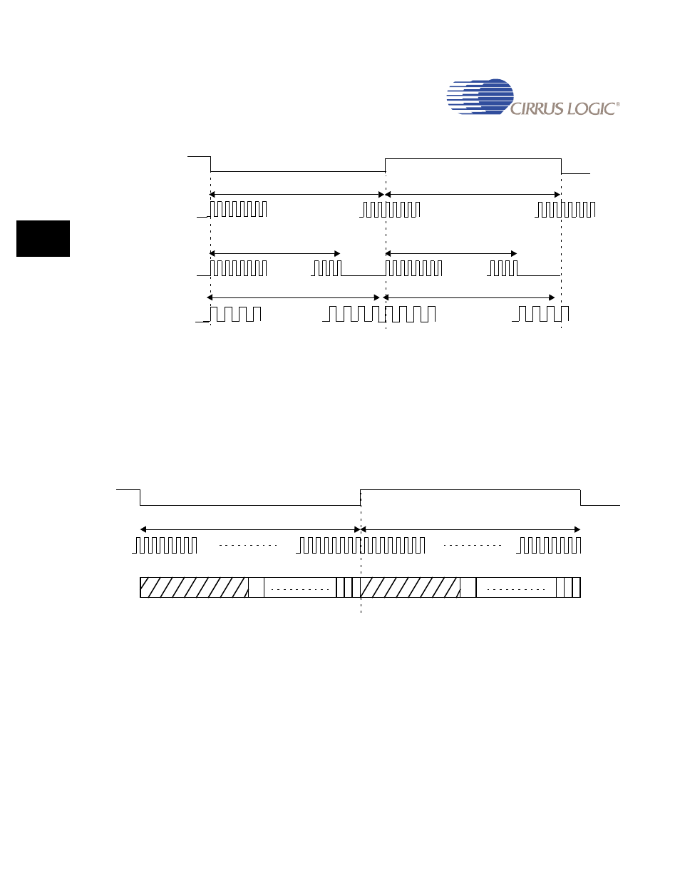
Figure 21-2. Bit Clock Generation Example
21.5.2 Example of Right Justified LRCK format
shows the frame format for Right Justified data. The word length is 16 in this
case and the MSB is transmitted first. The bit clock rate is 64x so the for the first 16 clock
cycles in each word there is no data as it is right justified in each word frame.
Figure 21-3. Frame Format for Right Justified Data
21.6 Interrupts
The I
2
S controller generates a single interrupt, I2SINTR to the ARM Core. This interrupt is a
combination (logical OR) of all TX and RX internal interrupts.
The transmitter generates 4 internal interrupts within the I
2
S controller. Each of these reflect
the status of the 3 individual TX FIFOs. These internal interrupts are as follows:
•
TX0 FIFO empty.
•
TX1 FIFO empty.
LRCKX
I
2
S
word
size = 32
...............
...............
32 pulses
32 pulses
I
2
S
word
size = 24
..........
24 pulses
24 pulses
..........
..........
16 pulses
16 pulses
..........
I
2
S
word
size = 16
Bitclk
Bitclk
Bitclk
2 1 0
15
2 1 0
15
LRCKX LEFT
LRCKX RIGHT
SCK
SDATA
BCR = 64x, 32 pulses left word
BCR = 64x, 32 pulses right word