I2s controller, 1 introduction, R 21. i – Cirrus Logic EP93xx User Manual
Page 657: 1 introduction -1, Figure 21-1. architectural overview of the i, Chapter 21, S controller, Chapter 21 21 i
DS785UM1
21-1
Copyright 2007 Cirrus Logic
2
1
2
1
21
Chapter 21
21
I
2
S Controller
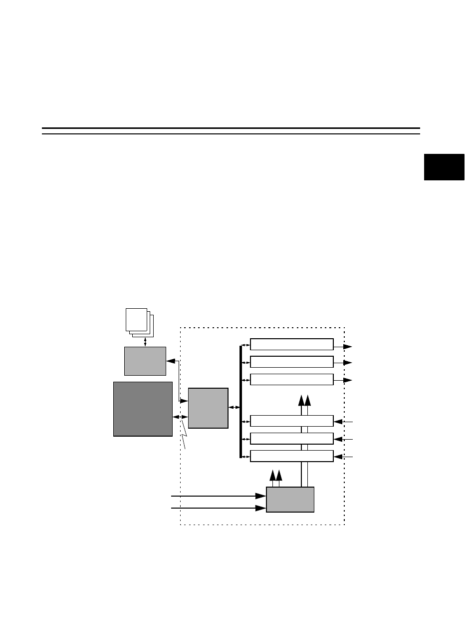
21.1 Introduction
The I
2
S controller is used to stream serial audio data between the external I
2
S CODECs’,
ADCs/DACs, and the ARM Core. It consists of 3 transmitter channels and 3 receiver
channels. Each channel handles a single stereo stream. The transmitter and receiver are
completely independent of each other and are programmed separately. Each channel (RX
and TX) has its own set of addressable registers which allows access through the ARM APB
or DMA accesses.
gives an architectural overview of the I
2
S controller.
2
S
controller.input and output signals.
The i2s_audioclk_mux section performs gating on the incoming audio clocks based on the
settings within the TX and RX clock configuration registers and delivers a known clock
definition to the rest of the I
2
S controller.
Figure 21-1. Architectural Overview of the I
2
S Controller
I2S_APB/
TX Channel 1
TX Channel 2
RX Channel 0
RX Channel 1
RX Channel 2
sdo0
sdo1
sdo2
sdi0
sdi1
sdi2
ARM
AMBA APB
BUS
I2S_AudioClk_Mux
TX Channel 0
lrckt & sckt to
each TX channel
lrckr & sckr
to each RX
channel
DMA IF
I
2
S
DMA
Controller
Memory
6 DMA Channels
Core
lrck
sck