Table 25-2 – Cirrus Logic EP93xx User Manual
Page 745
DS785UM1
25-7
Copyright 2007 Cirrus Logic
Analog Touch Screen Interface
EP93xx User’s Guide
2
5
2
5
25
The algorithm begins by putting the touch screen into its touch detect settling state for up to
1024
μ
sec as determined by the DLY value in the TSSetup register. After the delay value, the
algorithm moves to the touch detect state. The switches in the settling and touch detect
states are controlled by the TSDetect register value. The algorithm stays in the touch detect
state until a touch is detected.
Once a touch is detected, the algorithm moves to the discharge X state and stays there for up
to 1024
μ
sec as determined by the DLY value in the TSSetup register. The switches in the
discharge state are controlled by the TSDischarge register value. After the delay value, the
algorithm moves to the sample X state. In this state, the analog switches are set to the
TSXSample register. For example, for an 8-wire touch screen, VDD voltage is applied to X+,
with X- held at ground potential, and the SX+ and SX- lines are connected as the reference
for the A / D. The sample X state is also held for up to 1024
μ
sec as determined by the DLY
value in the TSSetup register before any samples are taken.
At the end of the delay, the logic begins to take A / D samples. The initial read is a convert
command and data from the initial sample is discarded. The number of samples taken is 4, 8,
16, or 32 as determined by the NSMP value in the TSSetup register. Each sample is
compared with a min and max register to determine the range of samples taken. The min
register is initialized to a value of 4095 and the max register is initialized to a value of 0. Any
data points sampled will fall within this range and the min and max stored sample values will
be adjusted based on the comparison. In addition, as the samples are taken, a running
accumulator adds each 12-bit sample to a 17-bit total. After all samples are taken, the stored
min is subtracted from the stored max for the sample set. The difference is compared to 4, 8,
12, 16, 24, 32, 64, or 128 as determined by the DEV value in the TSSetup register. If the
range exceeds the deviation allowed, the results are scrapped and the logic starts over with
initialization and detection of a valid touch. This allows a data set to be screened for bad
points (possibly caused by noise or removing a press) that would adversely affect an average
value. If the range does not exceed the maximum deviation allowed, the resulting value in the
accumulator register is shifted by 2, 3, 4, or 5 places to divide by the number of samples as
determined by the NSMP value in the TSSetup register. This generates the average for the
sample set for a new X value.
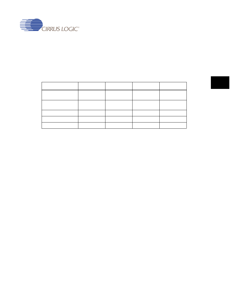
Table 25-2. Touch Screen Switch Register Configurations
Register Name
4-Wire
5-Wire
7-Wire
8-Wire
TSDetect
(If TSSetup2.S28EN = 0)
0x0040_3604
0x0042_0620
0x0042_0620
0x0040_3604
TSDetect
(If TSSetup2.S28EN = 1)
0x1040_3604
0x1042_0620
0x1042_0620
0x1040_3604
TSDischarge
0x0007_FE04
0x0002_2E20
0x030A_3020
0x0007_FE04
TSXSample
0x0008_1604
0x001D_D620
0x0318_5020
0x0308_1004
TSYSample
0x0010_4601
0x002D_B620
0x0328_3020
0x0C10_4001