2 reset control, 1 registers, 2 reset control -4 – Cirrus Logic EP93xx User Manual
Page 652: 1 registers -4, Table 20-1. real time clock register memory map -4
20-4
DS785UM1
Copyright 2007 Cirrus Logic
Real Time Clock With Software Trim
EP93xx User’s Guide
2
0
2
0
20
20.1.2 Reset Control
The RTC block level reset operation is a bit complicated. The reset strategy is for the time-
keeping part of the RTC to survive a system reset, and only be initialized by a power-on reset.
The RTC interrupt enable is cleared by a user reset, so that a time count match (alarm
interrupt) would disable with system reset.
The following register is initialized only by PRSTn: RTCSWComp
The following registers are initialized by PRSTn: RTCData, RTCMatch, RTCLoad, and
RTCCtrl.
20.1 Registers
Register Descriptions
RTCData
Address:
0x8092_0000 - Read Only
Default:
0x0000_0000
Definition:
RTC Data Register. Contains the 32 bit RTC counter value. This counter is
incremented by the 1 Hz clock output from the RTC Trim module.
Bit Descriptions:
RTCDR: Counter
value.
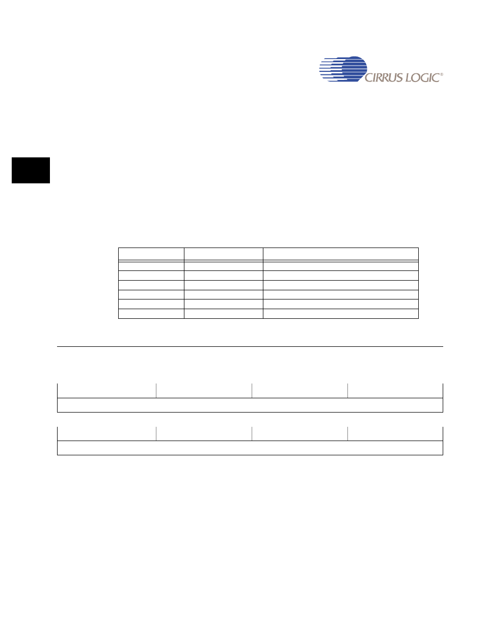
Table 20-1. Real Time Clock Register Memory Map
Address
Name
Description
0x8092_0000
RTC Data Register
0x8092_0004
RTC Match Register
0x8092_0008
RTC Status/EOI Register
0x8092_000C
RTC Load Register
0x8092_0010
RTC Control Register
0x8092_0098
RTC Software Compensation
31
30
29
28
27
26
25
24
23
22
21
20
19
18
17
16
RTCDR
15
14
13
12
11
10
9
8
7
6
5
4
3
2
1
0
RTCDR