Data displa ys – IDEC High Performance Series User Manual
Page 619
WindO/I-NV2 User’s Manual
10-107
7 Alarm List Display
10
Data Displa
ys
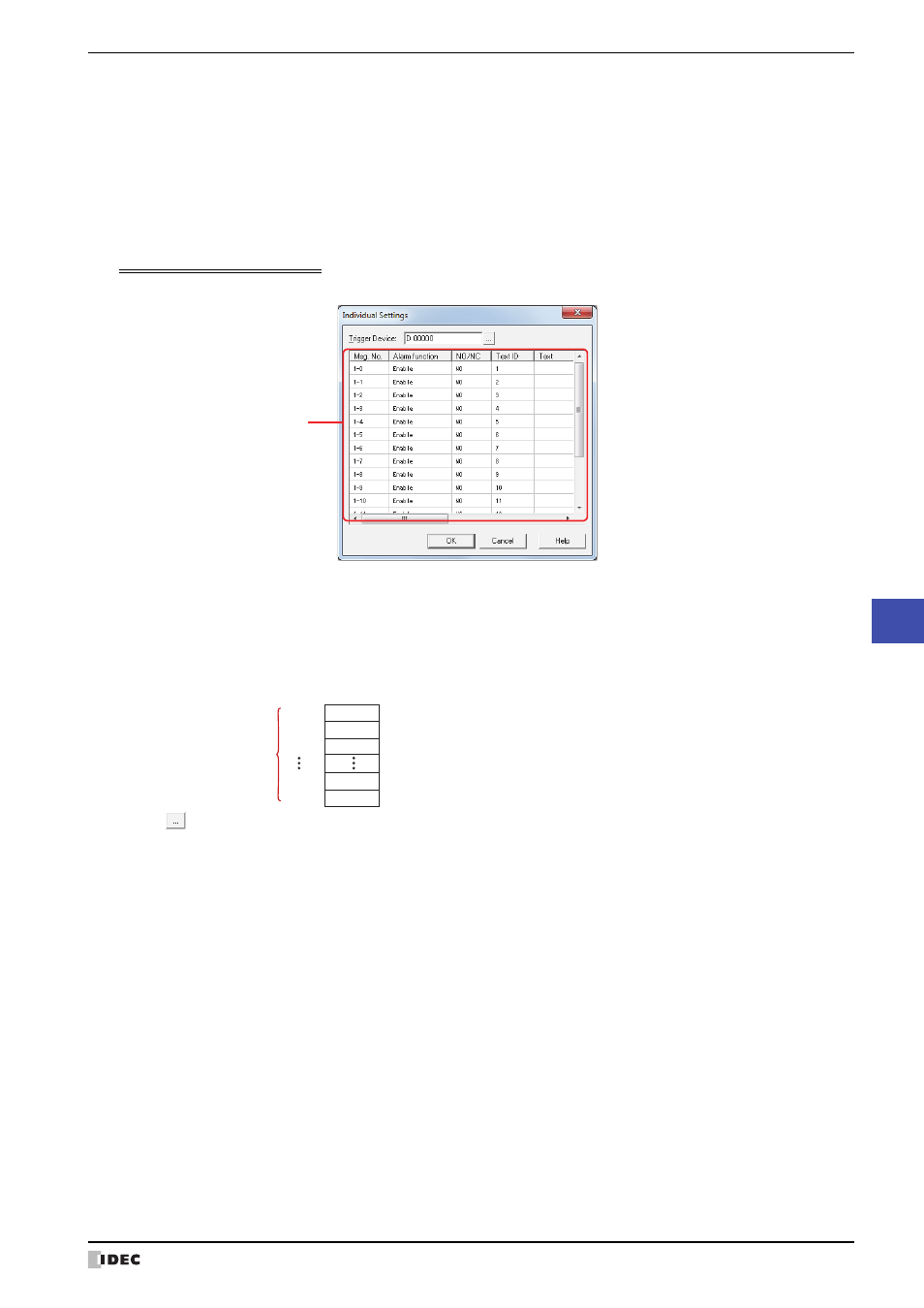
Individual Settings Dialog Box
The Individual Settings dialog box is used to configure the conditions to display the messages.
■
Trigger Device
Specifies the word device to use as the condition to display messages. The word device bits correspond to the
message numbers.
Click
to display the Device Address Settings dialog box. For the device address configuration procedure, refer
to Chapter 2 “5.1 Device Address Settings” on page 2-67.
When Serial is selected for Device Setting Method on the List tab, the trigger devices for block numbers after the
block number being registered or edited are automatically changed with the configured trigger device as the starting
address.
■
(Settings)
Insert:
Inserts the block settings in the position selected on the list.
Select the block number at the position to insert the settings in the list and click this button to
display the Individual Settings dialog box. For details, refer to “Individual Settings Dialog Box” on
page 10-107.
The settings at the insertion point shift down one line. Settings cannot be inserted if all block
numbers are configured.
Delete:
Deletes the registered settings from the list.
Select a block number on the list and click this button to delete the selected settings from the list.
(Settings)
Example: When the number of blocks is 1 and D 0 is specified as the trigger device
Message number 1-0 device bit is D0-0, message number 1-1 device bit is D0-1, up to message number
1-15 device bit which is D0-15.
D0-0
D0-1
D0-2
D0-14
D0-15
1-0
1-1
1-2
1-14
1-15
Block 1
16 channels
Msg. No.
Device bit
Msg. No.:
Displayed as (Block No.)-(Message No.).
Alarm function:
Selects whether or not to use the alarm function. Double clicking the cell switches between
Enable and Disable.
Enable: Monitors the state of the device bit configured for the channel and displays the message.
Disable: The device bit is not monitored and the message is not displayed.
NO/NC:
Selects the alarm detection condition. Double clicking the cell switches between NO and NC.
NO:
Displays the message when the monitored bit changes from 0 to 1.
NC:
Displays the message when the monitored bit changes from 1 to 0.
Text ID:
Shows the Text Manager ID number (1 to 32000) to use for the message.
The text ID is sequentially configured starting with the text ID configured by Start Text ID on
the List tab.
Text:
Shows the text for the specified text ID.
Only shows the first line of text when the text registered to the text ID has multiple lines.