Plc link connection types, 2 plc link communication settings, Plc link communication settings -2 – IDEC High Performance Series User Manual
Page 104
1 PLC Link Communication
3-2
WindO/I-NV2 User’s Manual
●
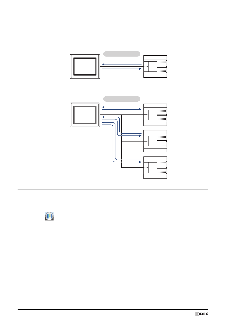
PLC Link Connection Types
There are two basic types of connections. 1:1 Communication, where an external device is connected to a
MICRO/I; and 1:N Communication, where multiple external devices are connected to a MICRO/I.
■
1:1 Communication
The MICRO/I is connected to a single external device.
■
1:N Communication
The MICRO/I is connected to multiple external devices.
1.2 PLC Link Communication Settings
The external devices connected to the MICRO/I and connection types are selected on the Select Host I/F Driver dialog
box, or the Change Host I/F Driver dialog box.
• When creating new project data by following displayed dialog boxes and configuring settings step by step, by
clicking
, and then clicking New, the Select Host I/F Driver dialog box is displayed. For details, refer to
Chapter 4 “Create new project data by using the interactive quick start” on page 4-1.
• Click Host I/F Driver on the status bar to display the Change Host I/F Driver dialog box. For details, refer to
Chapter 4 “Changing Host I/F Drivers” on page 4-22.
Specify Manufacturer and Protocol for each CPU Unit
of the external device. For details
regarding the correspondence model, refer to the "External Device Setup Manual."
*1 Unit names vary based on the manufacturer of the external device.
MICRO/I
External device
Read
Write
PLC Link Communication
MICRO/I
Station No.1
Station No.2
Station No.3
External device
Read
Write
Read
Write
Read
Write
PLC Link Communication