3 operating modes, Operating modes -4, 3operating modes – IDEC High Performance Series User Manual
Page 28
3 Operating Modes
1-4
WindO/I-NV2 User’s Manual
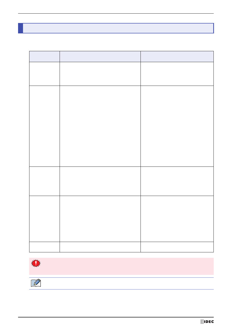
The MICRO/I includes multiple modes, so you switch between modes as and when necessary. These modes are called
operating modes. The functions and the operations and conditions for switching are as follows.
3
Operating Modes
Mode
Functions
Conditions required for
switching to the mode
Run Mode
This is the mode at the time of executing project
data. The created screen is displayed.
• Turn ON the power to the MICRO/I.
• Press [Run] on the Top Page of system
mode or on the System Menu.
• The download of the project data is
completed.
System Mode
Perform initial settings, clock settings, self-diagnosis,
etc. for the MICRO/I.
• Display the Maintenance Screen with the
following methods and press [System
Mode].
HG2G-S/-5S/-5F, HG3G/4G, HG1F:
Press the upper-left
corner of the MICRO/I
screen for three
seconds or more.
HG2F/2S/3F/4F:
Simultaneously press
the upper-left and
upper-right corners of
the MICRO/I screen.
• Using the screen switching button, multi-
buttons, screen switch or multi commands,
switch to the System Mode.
• All data is cleared using WindO/I-NV2.
• Write the System Area 1 Display screen
number (address+0) to FFFFh.
Monitor Mode
Monitor Mode is used for monitoring values of
devices using WindO/I-NV2.
In this mode, the following message blinks on the
bottom-left of the MICRO/I screen.
HG2G-S/-5S/-5F, HG3G/4G: Monitor Mode
HG1F/2F/2S/3F/4F:
Debug Mode
On the WindO/I-NV2 Online tab, in the
Monitor group, click Start Monitor.
Simulation Mode
This mode simulates the external device's device
values.
In this mode, the message "Simulation Mode" blinks
on the bottom-left of the MICRO/I screen.
• Press the following buttons in System Mode.
HG2G-S/-5S/-5F, HG3G/4G:
[Simulate] on the Top
Page
HG1F/2F/2S/3F/4F:On the System Menu,
[Debug], [Simulation],
[Start]
• While monitoring in WindO/I-NV2, on the
[Online] tab, in the [Monitors] group, click
[Start Simulation].
Data Transfer
Transferring data between a computer and the
MICRO/I.
• Download project data.
• Upload project data.
• When switched to System Mode, operation of the MICRO/I stops.
• To display the Maintenance Screen, the Enable Maintenance check box from the System Settings
tab of the Project Settings dialog box must be checked.
For details about Maintenance Mode, refer to Chapter 33 “1 Maintenance Screen” on page 33-1.