Expansion switch block – IDEC High Performance Series User Manual
Page 1394
6 HG2S
34-78
WindO/I-NV2 User’s Manual
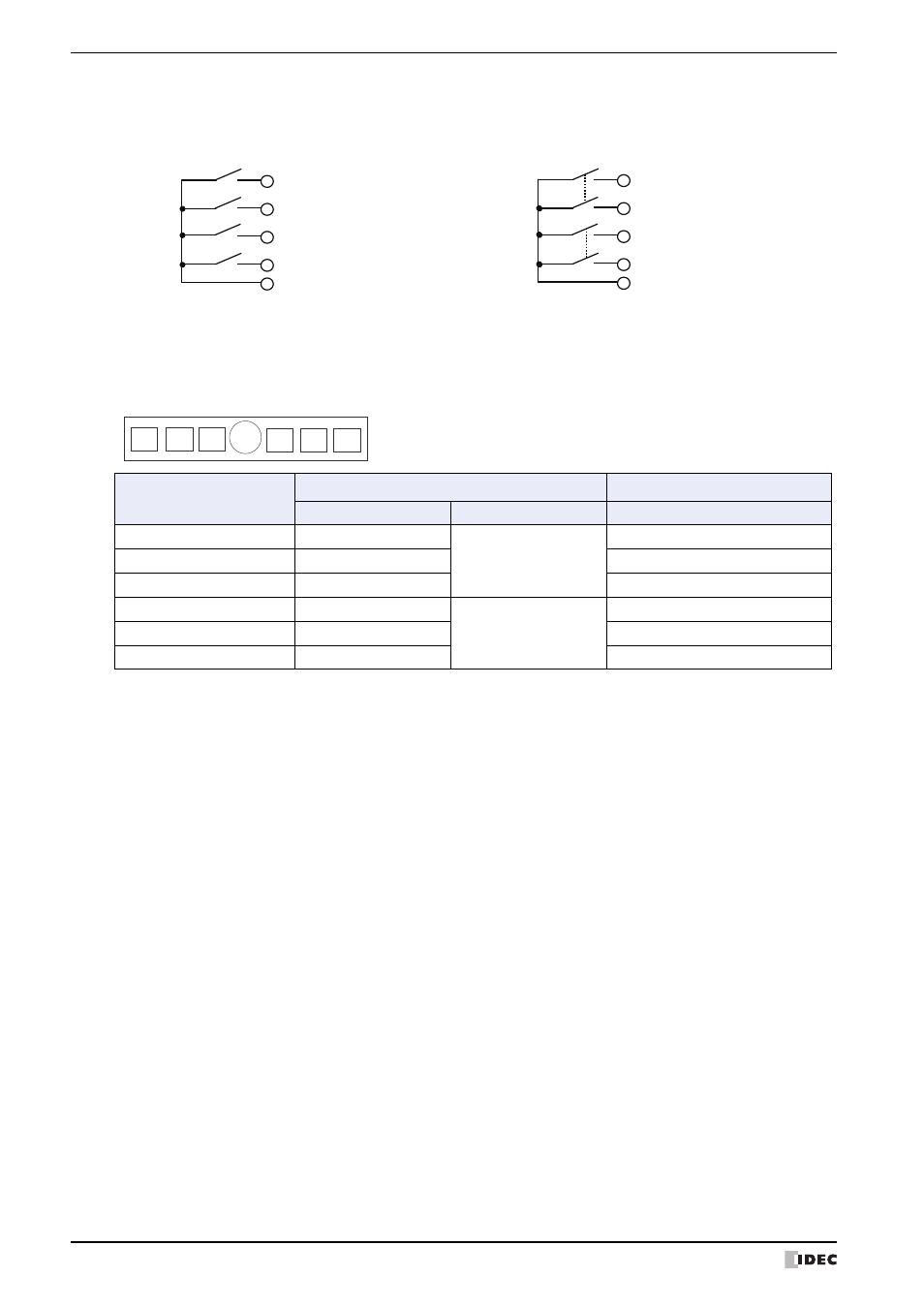
3 to 6. Push-button Switchse (C1, C2, D1, D2)
●
Expansion Switch Block
Switches at E1 through E6 are allocated to expansion I/O relays in the CPU and correspond to relay signals shown in
the table below. These signals are not sent out to the cable.
*1 One 2NO switch can be installed in each of the left switch block (E1 to E3) and the right switch block (E4 to E6). Contacts 1
of 1NO switches at E1 to E6 are allocated to expansion input relays LPX0 to LPX2 and LPX4 to LPX6. Contacts 2 of the only
2NO switches in the left and right switch blocks are allocated to LPX3 and LPX7, respectively.
*2 External output relays can be used to light the LED in illumi-nated pushbuttons and pilot lights installed at E1 to E6.
Example: When switches with 1NO contact are
installed at C1, C2, D1, and D2.
Example: When selector or key selector switches with
2NO contacts are installed at C2 and D1.
5 D1
24
6 D2
25
3 C1
26
4 C2
27
28
D-sub 37P
Pin No.
24
25
Contact 1
26
27
28
Contacr 2
Contact 1
Contact 2
5 D1
4 C2
D-sub 37P
Pin No.
Switch Position
Expansion Input Relay
Expansion Output Relay
Contact 1
Contact 2
LED Lighting
E1
LPX0
LPX3
LPY0
E2
LPX1
LPY1
E3
LPX2
LPY2
E4
LPX4
LPX7
LPY4
E5
LPX5
LPY5
E6
LPX6
LPY6
A
E1
E2
E3
E4
E5
E6