IDEC High Performance Series User Manual
Page 1295
WindO/I-NV2 User’s Manual
32-3
2 Internal MICRO/I Devices
32
In
tern
al
Devices
■
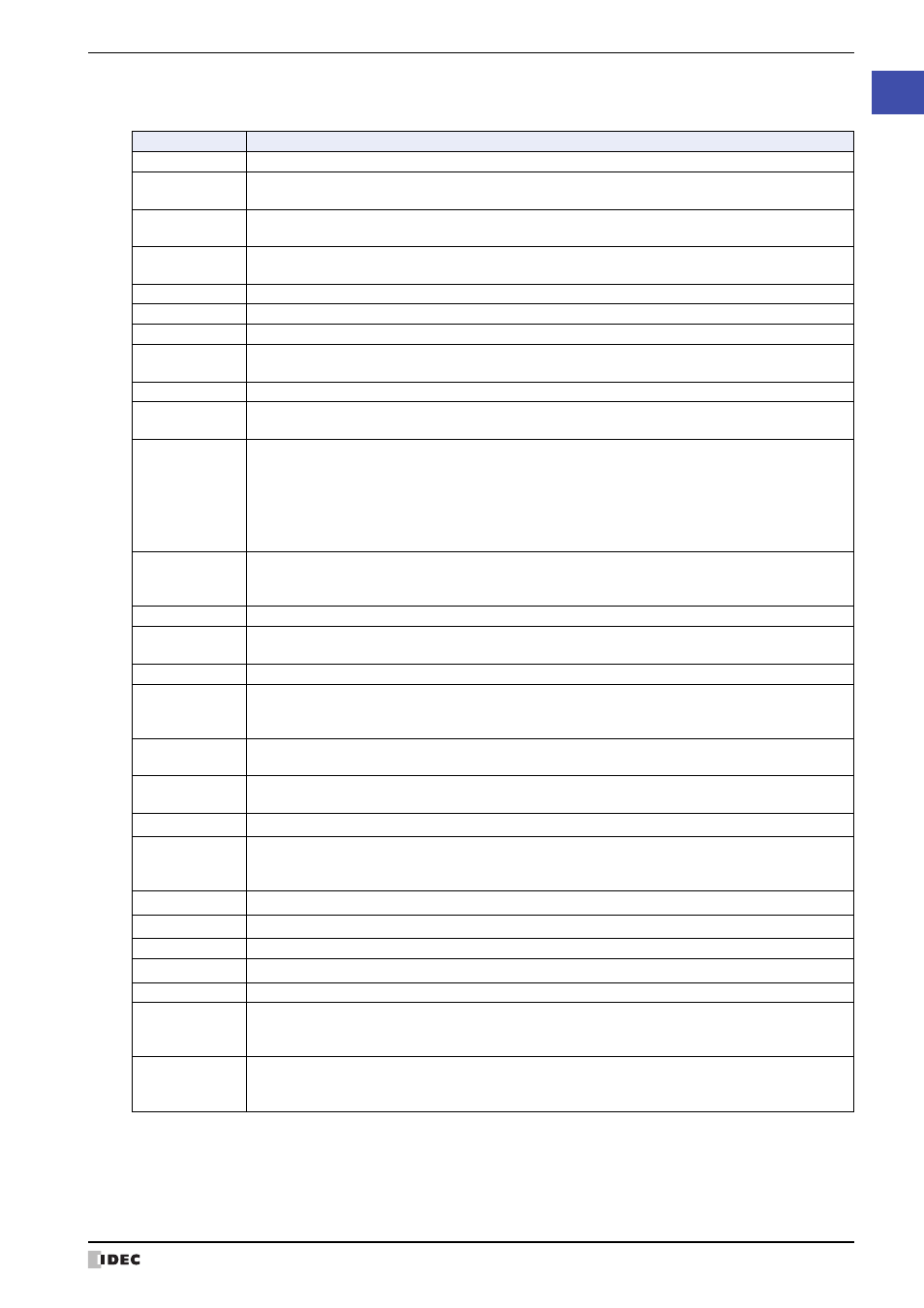
HG Special Relay (LSM)
The 64 points of the HG special relay are used to perform the following special operations.
*2 HG2G-5F, HG3G/4G only
*3 HG2G-S/-5S, HG1F/2F/2S only
HG Special Relay
Function/Part
LSM0
Normally set to 1.
LSM1
1 only on the second scan when Base Screen is switched.
It also operates when switching text group or user account, or resetting the display screen.
LSM2
1 only on the first scan when Base Screen is switched.
It also operates when switching text group or user account, or resetting the display screen.
LSM3
0 only on the first scan when Base Screen is switched.
It also operates when switching text group or user account, or resetting the display screen.
LSM4
Alternates between 0 and 1 with each scan.
LSM5
1 only on the first scan when Popup Screen is opened.
LSM6
1 while touch panel is pressed.
LSM7
Alternates between 0 and 1 each time data is read (read scan) from all the external devices being
used.
LSM8
After powering ON value is 1 until the initially displayed screen switches to another screen.
LSM9
When value changes from 0 to 1, the backup data stored in flash memory is restored.
When it becomes 1 value does not become 0 until the Touch is reset or 0 is written.
LSM10
When switched from 0 to 1, the current backlight setting and the following data are transferred to the
flash memory:
•Keep relays and keep register data configured in the data storage area
•Keep relays 0 through 1013 and keep registers 0 through 1023
Once LSM10 switches to 1, it does not change to 0 until MICRO/I recycles power or 0 is written to
LSM10.
LSM11
Changes from 0 to 1 when the Base Screen is switched, after the values of all the external devices
being used are read, and remains 1 until there is a switch to another screen.
It also operates when switching text group or user account, or resetting the display screen.
LSM12
1 only on the first scan when Popup Screen is closed.
LSM13
Value becomes 0 when Popup Screen is opened, and then changes from 0 to 1 after all the values of
all the external devices being used by that Popup Screen are read.
LSM14 to 17
Reserved
LSM18
When value changes from 0 to 1, access to USB flash drive is stopped. The access state can be
checked with the value of LSM19.
When it becomes 1 value does not become 0 until the MICRO/I is reset or 0 is written.
LSM19
Value is 1 while there is access to USB flash drive. If value is 0 the USB flash drive can be safely
ejected.
LSM20
Access to the Memory Card stops when this bit is switched from 0 to 1. The access state can be
checked with the value of LSM21.
LSM21
Bit is 1 during Memory Card access. When 0, the memory card can be removed.
LSM22
This is the Operation Log function. When data in excess of the amount that can be recorded in one
operation occurs, the value becomes 1.
When it becomes 1 value does not become 0 until the MICRO/I is reset or 0 is written.
LSM23
This bit is 1 while copied.
LSM24
This bit is 1 while outputting the data to the Memory Card.
LSM25 to 26
Reserved
LSM27
Stops playing the sound file when this bit is turned from 0 to 1.
LSM28 to 29
Reserved
LSM30
If LSM30 is OFF, all files (including the subfolders with files) under the source folder will be copied to
the destination folder. If LSM30 is ON, only the files (excluding the subfolders with files) under the
source folder will be copied to the destination folder.
LSM31
If LSM31 is turned ON while copying the files (excluding the subfolders with files) from the source
folder to the destination folder, MICRO/I will complete the copy process of the file while remaining files
in the source folder will not be copied.