2 dm link communication settings, Dm link communication settings -5, Communic ation – IDEC High Performance Series User Manual
Page 107
WindO/I-NV2 User’s Manual
3-5
3 DM Link Communication
3
Communic
ation
■
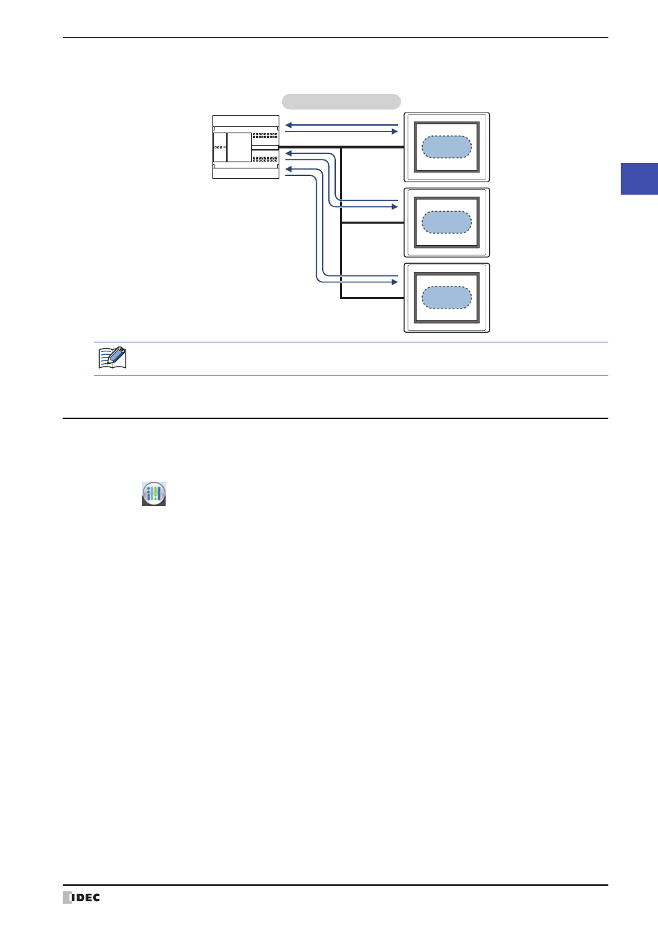
1:N Communication
The external device is connected to multiple MICRO/I.
3.2 DM Link Communication Settings
DM Link Communication settings are selected on the Select Host I/F Driver dialog box, or the Change Host I/F Driver
dialog box.
• When creating new project data by following displayed dialog boxes and configuring settings step by step, by
clicking
, and then clicking New, the Select Host I/F Driver dialog box is displayed. For details, refer to
Chapter 4 “Create new project data by using the interactive quick start” on page 4-1.
• Click Host I/F Driver on the status bar to display the Change Host I/F Driver dialog box. For details, refer to
Chapter 4 “Changing Host I/F Drivers” on page 4-22.
Select IDEC HG System in Manufacturer, and then select DM Link (1:1) or DM Link (1:N) in Protocol.
Station No.1
Station No.2
Station No.3
MICRO/I
Dedicated DM
Link memory
Dedicated DM
Link memory
Dedicated DM
Link memory
External device
Read
Write
Read
Write
Read
Write
DM Link 1:N Communication
The Event Transmission function cannot be used with 1:N communication.