Configuring a bypass lsp, Protected by a bypass lsp is described in, Configuring a protected lsp – Brocade Multi-Service IronWare Multiprotocol Label Switch (MPLS) Configuration Guide (Supporting R05.6.00) User Manual
Page 88
64
Multi-Service IronWare Multiprotocol Label Switch (MPLS) Configuration Guide
53-1003031-02
MPLS Fast Reroute using facility backup over a bypass LSP
1
Configuring a protected LSP
To acquire the protection of one or more bypass LSPs along its route, an LSP that is requesting
facility backup checks the interfaces that it traverses for the availability of a bypass LSPs that meet
its requirements. (A Fast Reroute LSP that needs facility backup must request it. Refer to
“Protecting MPLS LSPs through a bypass LSP”
for the configuration steps.) The requesting LSP
checks all of the bypass LSPs on the outbound interface of each router and selects a candidate
bypass LSP that best meets its criteria so that, when the protected LSP fails, its traffic immediately
switches to the bypass LSP that is upstream from the point of failure.
When an LSP is enabled for Fast Reroute, the CLI enters the configuration level for Fast Reroute,
which has the option for requesting facility backup. Entering the keyword facility-backup in the Fast
Reroute level configures the LSP to request facility backup as provided by a bypass LSP.
Subsequently, for the LSP to acquire the protection of a bypass LSP, that bypass LSP must have the
bandwidth, the constraints, the route (for the merge point), and other criteria that the LSP requires.
Furthermore, the configuration of the bypass LSP itself must list the interface on the router where
the candidate LSP and the bypass LSP first intersect. The description of linking a Fast Reroute LSP
to a bypass LSP is in
.
Configuring a bypass LSP
The crucial topics to understand for configuring a bypass LSP are the PLR, the merge point, and the
excluded interfaces. This section provides a detailed definition of these items and describes how
they relate to each other. Refer to
for the description of these topics.
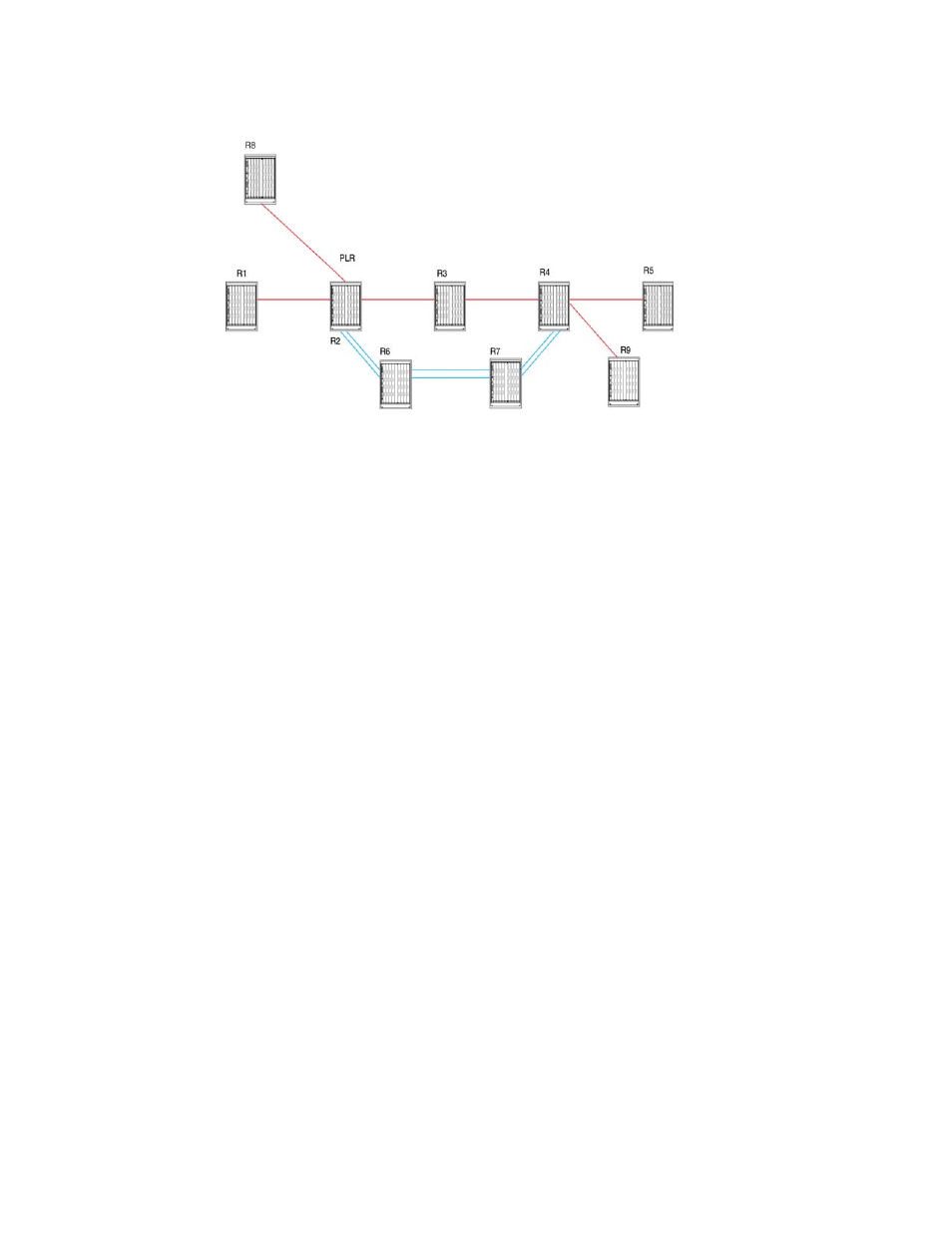
The PLR is the ingress of a bypass LSP. When a protected link breaks downstream from the PLR,
the bypass LSP carries the traffic of the LSPs it protects around the break. As shown in
,
the LSPs from R1 and R8 enter R2 (the PLR). The double line that originates at R2 and then
traverses R6 and R7 to terminate at R4 is the bypass LSP.
, the egress router for the protected LSPs is R5. Upstream from R5 is the point (R4)
where the bypass LSP terminates and merges the traffic back into the protected LSPs. This router
is the merge point.
In facility backup, the interfaces that go into this arrangement can belong to either:
•
The bypass LSP