Sample ldp configuration with vll, Router r1 – Brocade Multi-Service IronWare Multiprotocol Label Switch (MPLS) Configuration Guide (Supporting R05.6.00) User Manual
Page 449
Multi-Service IronWare Multiprotocol Label Switch (MPLS) Configuration Guide
425
53-1003031-02
Sample LDP configuration with VLL
2
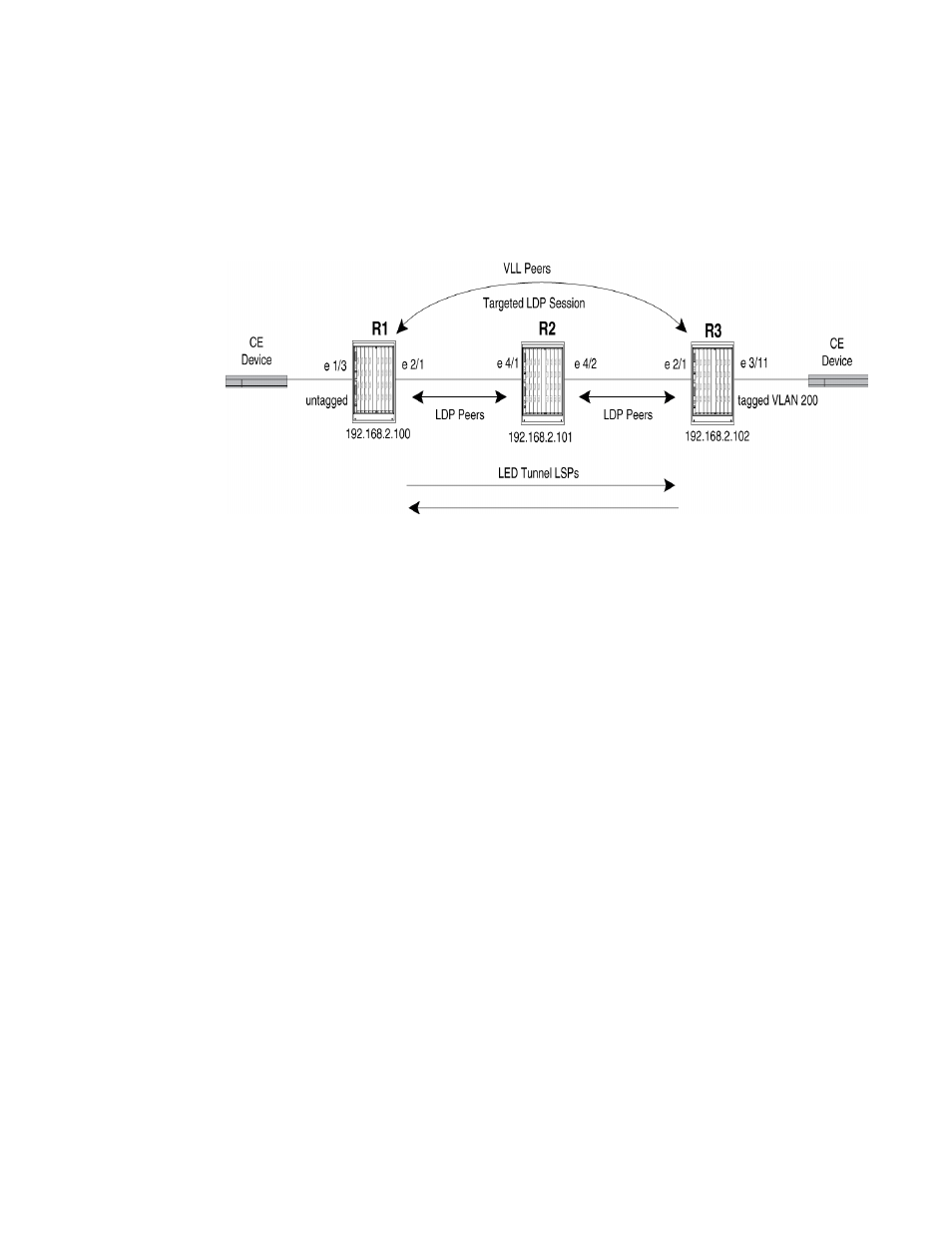
Sample LDP configuration with VLL
illustrates a sample Virtual Leased Line (VLL) configuration that uses LDP tunnel LSPs.
FIGURE 49
MPLS VLL configuration with LDP tunnel LSPs
In this example, routers R1 and R3 are Provider Edge (PE) routers configured as VLL peers. R1 and
R3 have established a targeted LDP session to exchange VLL label information. When this targeted
LDP session is established, each router advertises its locally assigned VC label and VC ID to its VLL
peer.
In addition, LDP sessions have been established between R1 – R2 and R2 – R3. LDP tunnel LSPs
exist in each direction between R1 and R3. When the CE device forwards a Layer 2 packet to R1,
the router assigns the packet to an LSP whose destination is R3. R1 encapsulates the packet as an
MPLS packet, adding a tunnel label and the VC label advertised to the router by R3. The MPLS
packet is then forwarded over the outbound interface indicated by the tunnel label to the next hop
in the LSP.
When the MPLS packet reaches R2, the penultimate LSR in the tunnel LSP, R2 pops the tunnel
label, leaving the packet with only the VC label, then forwards the packet to R3.
R3 examines the VC label in the packet. On R3, the VC label is mapped to the user-specified
endpoint for the VLL. In this example, the endpoint consists of VLAN ID 200 and interface 3/11. R3
then pops the VC label, tags the Layer 2 packet with VLAN 200, then forwards the packet out
interface 3/11.
In the opposite direction, R3 assigns traffic received from the CE device to a tunnel LSP destined
for R1, pushes tunnel and VC labels onto the packets, and forwards them to the next hop in the
LSP. When the packets reach R1, the router pops the VC label and forwards the Layer 2 packets out
the interface indicated by the VLL endpoint. In this example, the endpoint consists of interface 1/3,
so the packets are forwarded untagged out interface 1/3 to the CE device.
Router R1
The following commands configure Router R1 in
.