Brocade Multi-Service IronWare Multiprotocol Label Switch (MPLS) Configuration Guide (Supporting R05.6.00) User Manual
Page 554
530
Multi-Service IronWare Multiprotocol Label Switch (MPLS) Configuration Guide
53-1003031-02
How MPLS VLL works
4
W = mapped COS from internal priority (Z contributes to internal priority) using the COS encode
table
X = original outer VLAN COS
Y = original inner VLAN COS
Z = incoming EXP bits as described by Tunnel / VC label column = V or internal priority
or in the Tunnel/VC label column differentiates the behavior between when qos exp encode
policy is ON (default) or OFF.
or in the Outgoing packet Outer VLAN column differentiates the behavior between when qos
pcp encode policy is ON (default) or OFF.
CoS behavior for VLL raw mode
NOTE
This section assumes that the user understands how QoS works.
describes the expected Class of Service (CoS) behavior for VLL packets when VLL raw
mode is in effect.
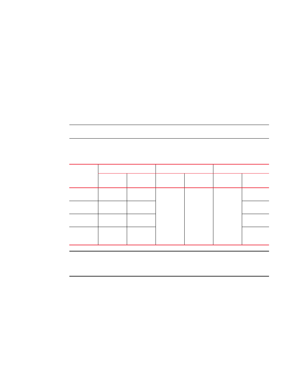
TABLE 83
Expected class of service behavior for VLL raw mode
VLL endpoints
Incoming packet
MPLS cloud
Outgoing packet
Outer VLAN
Inner VLAN
Tunnel/VC
label (Z)
Payload tag
Outer VLAN
Inner VLAN
Dual-tagged
to dual-tagged
X
Y
V or internal
priority
N/A
W or Z
Z
Single-tagged
to dual-tagged
X
N/A
Z
Untagged to
dual-tagged
N/A
N/A
Z
Dual-tagged
to
single-tagged
X
Y
N/A
NOTE
For more specific examples of CoS behavior for raw mode, see
dual-tagged to dual-tagged VLL endpoints”
dual-tagged to single-tagged VLL endpoints”
Legend for Table 83
V = mapped EXP bits from internal priority (X contributes to internal priority) using the EXP
encode table.
W = mapped COS from internal priority (Z contributes to internal priority) using the COS encode
table.
X = original outer VLAN COS
Y = original inner VLAN COS
Z = incoming EXP bits as described by Tunnel / VC label column = V or internal priority