Tracing a route through an mpls domain – Brocade Multi-Service IronWare Multiprotocol Label Switch (MPLS) Configuration Guide (Supporting R05.6.00) User Manual
Page 231
Multi-Service IronWare Multiprotocol Label Switch (MPLS) Configuration Guide
207
53-1003031-02
IP Traceroute over MPLS
1
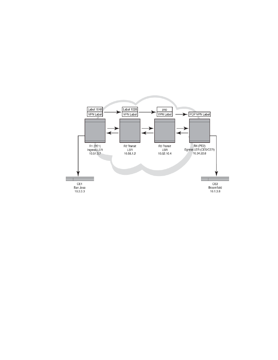
Tracing a route through an MPLS domain
shows an MPLS-enabled provider network consisting of four LSRs. R1 is the Provider
Edge (PE) ingress Label Edge Router (LER), R2 and R3 are transit LSRs, and R4 is the PE egress
LER. CE1 is a Customer Edge (CE) device in San Jose, and CE2 is the destination CE on another
customer site in Broomfield.
FIGURE 41
Traceroute in a Layer 3 VPN MPLS cloud
For the purpose of exemplifying the traceroute behavior in an MPLS domain, assume the following:
•
Customer traffic is tunneled through a Layer 3 VPN, and traffic within the MPLS core is
forwarded by label-switching only.
•
Traceroute is configured to generate ICMP responses per ICMP extensions and to use LSPs to
forward these messages.
•
The egress PE is a Brocade NetIron CER or a Brocade NetIron CES. Traceroute over a Layer 3
VPN configured to use ICMP extensions and LSPs are currently not supported when the egress
PE is a Brocade NetIron XMR or Brocade MLXe series router. Refer to
210 for more information.
•
The PE routers have knowledge of the IP address space on the customer side, whereas the
transit LSRs have no such knowledge.
•
The traceroute command is issued from CE1 to CE2 and reports the following information:
CE1# traceroute 10.1.3.8
Type Control-c to abort
Tracing the route to IP node (10.1.3.8) from 1 to 30 hops
1 <1 ms <1 ms <1 ms 10.51.3.7
2 <1 ms <1 ms <1 ms 10.56.1.2
MPLS Label=1048 Exp=7 TTL=1 S=0
MPLS Label=500000 Exp=7 TTL=1 S=1
3 <1 ms <1 ms <1 ms 10.52.10.4