P2mp lsp mechanism – Brocade Multi-Service IronWare Multiprotocol Label Switch (MPLS) Configuration Guide (Supporting R05.6.00) User Manual
Page 48
24
Multi-Service IronWare Multiprotocol Label Switch (MPLS) Configuration Guide
53-1003031-02
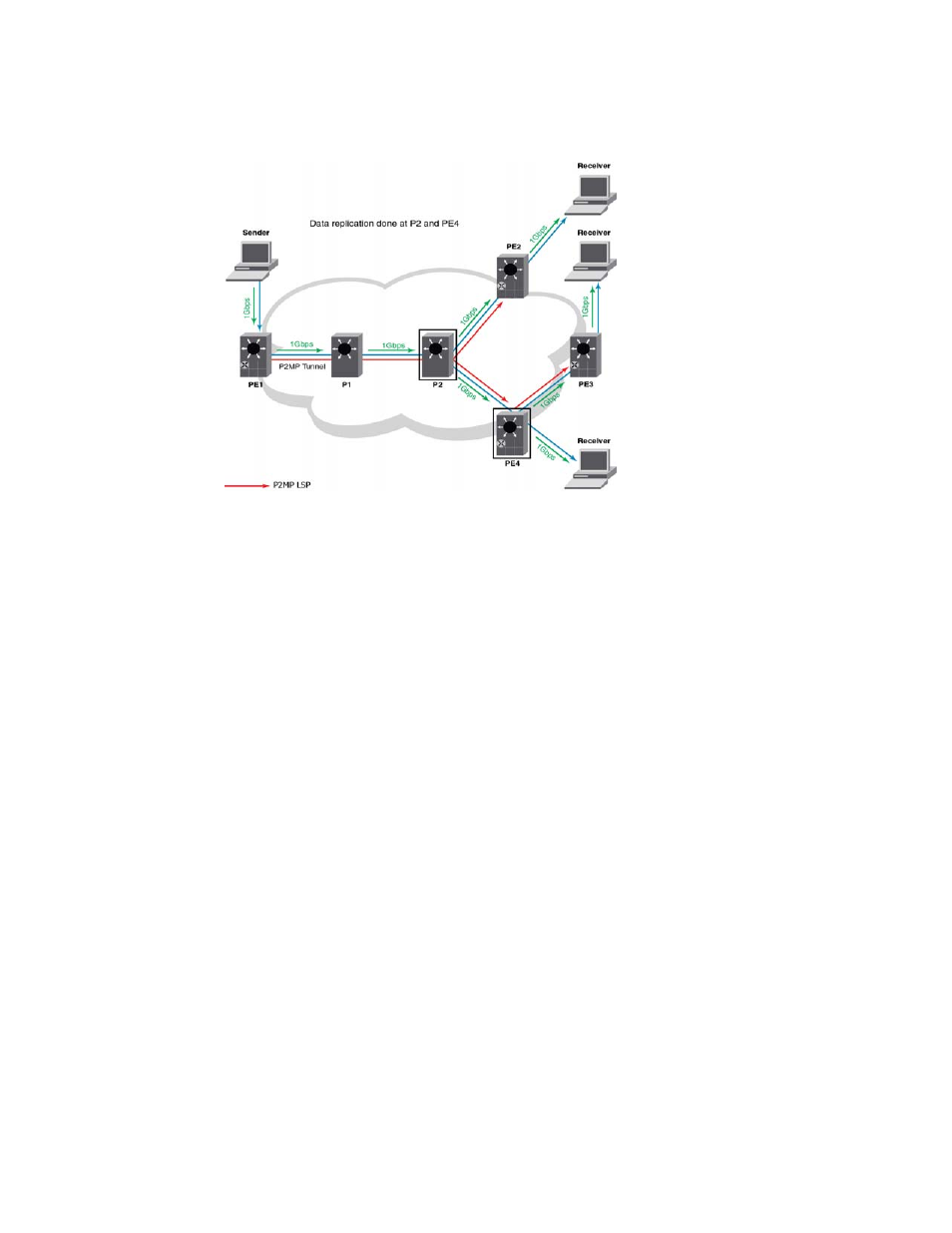
MPLS Point-to-Multipoint Traffic Engineering
1
displays a P2MP LSP originating at PE1 and ending at the three destinations PE2, PE3,
and PE4. As depicted in the topology diagram, the bandwidth utilization across the network is 1
Gbps.
The P2MP network consists of the following key elements in the topology.
•
PE1: The source or the root or the ingress label switch router (LSR).
•
P1 and P2: The transit routers.
•
PE2, PE3, and PE4: The destination or the leaves or the egress LSRs.
•
P2 is known as the branch node since it is has more than one directly connected downstream
LSRs.
•
PE4 is known as the bud node since it has directly connected local receivers. It also acts like a
branch router.
•
The path of a P2MP LSP from its ingress LSR to all egress LSRs is known as the P2MP tree. In
, the P2MP tree is rooted at PE1 with leaves at PE2, PE3 and PE4.
P2MP LSP mechanism
The P2MP LSP mechanism of forwarding MPLS traffic from a single source to multiple destinations
is explained using
.
1. PE1 sends out multicast data of 1 Gbps to the destination LSRs. Let us assume that PE1
learns that PE2, PE3, and PE4 form a P2MP LSP tree.
2. PE1 sends multicast data to reach P2. The path taken by the LSP is PE1—>P1—>P2.
3. At P2 and PE4, data gets replicated and the multicast data reaches the egress routers.
4. The egress routers route the multicast data to the specified receivers.