Ipv4 l3 vpn cam optimization overview – Brocade Multi-Service IronWare Multiprotocol Label Switch (MPLS) Configuration Guide (Supporting R05.6.00) User Manual
Page 759
Multi-Service IronWare Multiprotocol Label Switch (MPLS) Configuration Guide
735
53-1003031-02
IPv4 L3 VPN CAM optimization overview
6
IPv4 L3 VPN CAM optimization overview
This document reviews the functional specification for optimization of CAM programming for L3VPN
CAM for IPv4. This scheme is similar to the existing CAM programming of L3VPN CAM for IPv6. After
this optimization, L3VPN CAM look up for IPv4 packets is based on (VPN-ID, IP) instead of the
current implementation (port, VLAN, IP). This optimization brings efficient CAM usage as it saves
multiple CAM entries for same routes for the VPNs having multiple interfaces on the same PPCR.
In releases prior to NetIron R05.5.00, IP VPN CAM lookup is based on {port, VLAN, DST-IP} for
ingress traffic from CE side (VRF-lite). This is an inefficient way of CAM space utilization as it
requires each route to replicate for all endpoints of VRFs on the PPCR. IP VPN CAM optimization
resolves this issue by programming {VPN-ID, DST-IP} as CAM lookup keys.
The VPN-ID is derived from IFL-CAM (Service CAM) at pre-lookup (lookup step prior to route lookup)
stage where {port, VLAN} programs as its lookup keys. In this scheme, each route of a VRF
consumes only one CAM entry on a PPCR.
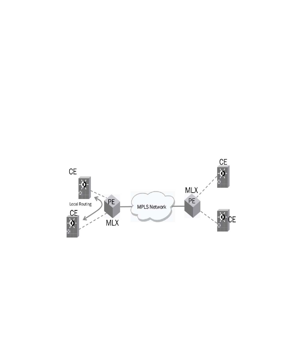
Network diagram
Figure 77
shows the topology of the IP VPN network.
FIGURE 84
IP VPN network
IPv4 Packet Flow for IPVPN after ingress side optimization
In VRF-lite, ingress direction packets come from CE devices to IP VPN endpoints on PE routers and
enter to the MPLS domain or route back to CE (local routing).
Figure 78
depicts the successful
processing of the ingress packets after optimization.