Figure – Brocade Multi-Service IronWare Multiprotocol Label Switch (MPLS) Configuration Guide (Supporting R05.6.00) User Manual
Page 585
Multi-Service IronWare Multiprotocol Label Switch (MPLS) Configuration Guide
561
53-1003031-02
Local VLL
4
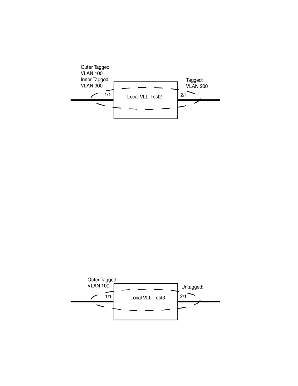
FIGURE 63
Local VLL “Test2” with one single-tagged VLAN and one dual-tagged VLAN
Brocade(config)# system-max ifl-cam 16384
Brocade(config)# router mpls
Brocade(config-mpls)# vll-local test2
Brocade(config-mpls-vll-lo-test1)# vlan 100 inner-vlan 300
Brocade(config-mpls-vll-lo-test1-vlan)# tagged ethernet 1/1
Brocade(config-mpls-vll-lo-test1-vlan)# vlan 200
Brocade(config-mpls-vll-lo-test1-vlan)# tagged ethernet 2/1
A shown in the following example, the user can use the show mpls vll-local detail command to see
that an IFL-ID has been created for this Local VLL instance.
Brocade# show mpls vll-local detail
VLL test2 VLL-ID 1 IFL-ID 4096
State: UP
End-point 1: tagged vlan 100 inner-vlan 300 e 1/1
COS: --
End-point 2: tagged vlan 200 e 2/1
COS: --
Example of a Local VLL configured for single-tagged and untagged VLAN traffic
the Local VLL named “Test3” contains Ethernet ports 1/1 and 2/1. Port 1/1 is a
member of VLAN 100 and port 2/1 is untagged. Because both ports belong to Local VLL “Test3,
traffic tagged with VLAN 100 is able to reach nodes attached to the untagged port and traffic from
the untagged port is able to reach nodes within VLAN 100.
FIGURE 64
Local VLL “Test3” with one tagged VLAN and one untagged port