Acl support for ve over vpls, Configuration considerations – Brocade Multi-Service IronWare Multiprotocol Label Switch (MPLS) Configuration Guide (Supporting R05.6.00) User Manual
Page 778
754
Multi-Service IronWare Multiprotocol Label Switch (MPLS) Configuration Guide
53-1003031-02
ACL Support for VE over VPLS
7
•
On each node, include the VPLS endpoint VLAN in the topology group VLAN as a member VLAN,
so the link from one of the nodes to the access box is blocked for Layer 2 loop avoidance.
Configure the master VLAN to have a Layer 2 protocol configuration, such as MRP/RSTP. Refer
to the topology group VLAN configuration for setting VPLS VLAN in the topology group VLAN.
•
The recommended configuration is VRRP-E with server virtualization.
•
Server virtualization helps the traffic in the backup node to be routed directly to the internet,
instead of being sent to the VRRP-e master over the MPLS uplink.
•
The no ip icmp redirects command must be configured in VRRP cass as well as VRRP-E cases
where server virtualization is not enabled.
ACL Support for VE over VPLS
VE over VPLS uses the same ACL commands as VE for VLANs to apply an Pv4 ACL on VE over VPLS
interfaces to filter both switched and routed L3 and L4 traffic in incoming and outgoing directions.
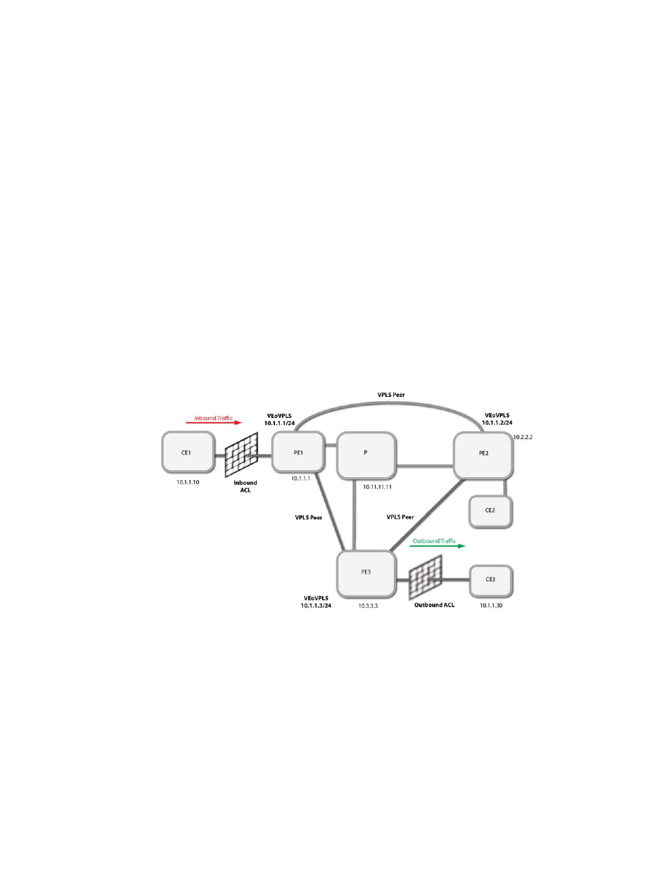
FIGURE 91
Sample VE over VPLS topology using ACLs
- Solid Grid: Inbound ACL to filter traffic incoming to PE1 VEoVPLS interface 10.1.1.1
- Blurred Grid: Outbound ACL to filter traffic outgoing from PE3 VEoVPLS interface 10.1.1.3
- 10.1.1.1, 10.2.2.2, 10.3.3.3, 10.11.11.11 are loopback addresses of PE1, PE2, PE3 and P nodes.
Configuration Considerations
Consider the following when configuring VE over VPLS ACLs.