Rockwell Automation GMLC Reference Manual User Manual
Page 781
Publication GMLC-5.2 - November 1999
744
Using the RIO Adapter Option
1. Open the GML Commander diagram.
2. Double-click on the Configure Cam block used to execute the appro-
priate profile. The Configure Cam dialog box opens, displaying the
starting and ending points of that profile in the cam tables.
Put the number of sequential cam table values to be transferred in the low
byte of word 2 of the BTW data file for the transfer.
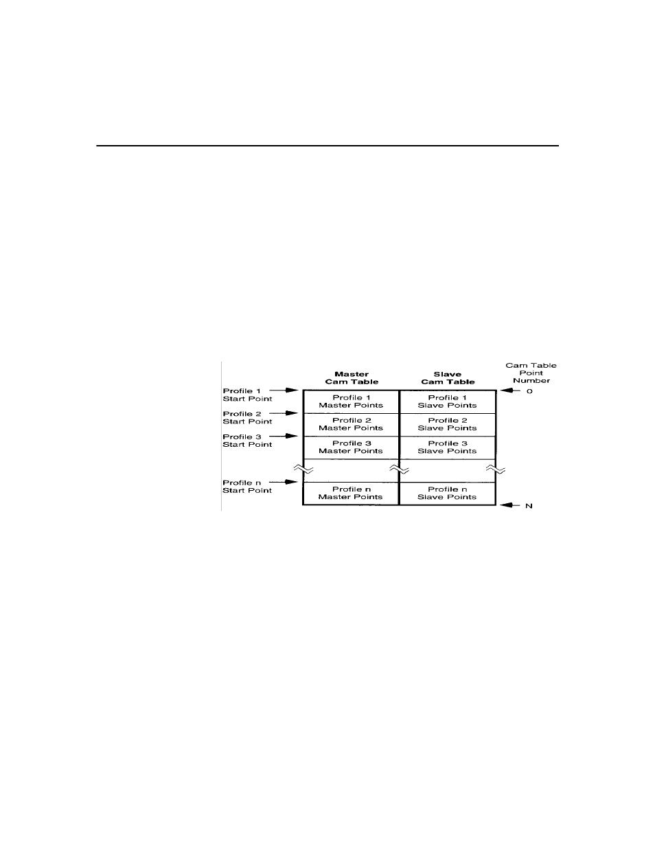
Your motion controller contains two cam tables, that can be used to store
many individual time-lock and/or position-lock cam profiles. The master
cam table stores time values (for time-lock cams) or master axis positions
(for position-lock cams), while the slave cam table stores the
corresponding slave axis positions, as shown below.
N = 1999 for iCODE V2.3 and earlier;
12,999 for iCODE V 3.0 and later
The cam tables can store any number of individual profiles of any length
as long as the total number of points for all profiles does not exceed the
capacity of the table. If you selected i
CODE
version 3.0 or later in the
General page of the Configure Control Options dialog box, each cam
table can contain up to 13,000 points numbered 0 through 12999. If you
selected i
CODE
version 2.3 or earlier, each cam table can contain up to
2,000 points numbered 0 through 1999.