Diagrams and blocks, Block palettes, Color code for blocks – Rockwell Automation GMLC Reference Manual User Manual
Page 60
Publication GMLC-5.2 - November 1999
Understanding Your Tools
23
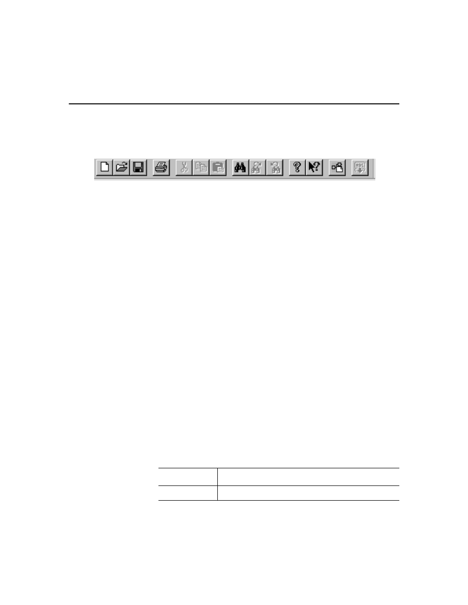
By default the Main Toolbar is enabled when COmmander is invoked.
You can disable or re-enable by selecting Toolbars from the View or Tools
menu. You can click on any button on the toolbar to see its function.
Diagrams and Blocks
A diagram is a sequence flow of events and is composed of tags
(definitions), blocks and connections. Tags describe the characteristics of
data defined fields. Blocks represent actions and decisions. Connections
link blocks in a specific order to show relationships and program flow.
Blocks are copied to the diagram from one of the several block palettes.
Using the available tools, you create a diagram and print it for reference
or save it for retrieval and later editing. Diagrams are translated to script
to assure syntactical correctness.
Block Palettes
The color-coded building blocks that contain GML Commander functions
are the graphical elements you use to create a diagram. These blocks are
contained in logical groups called palettes. Palettes are selected for
display and can be positioned anywhere on the screen in the same way as
Windows toolbars.
For instructions on selecting and placing blocks in a diagram, refer to the
Working with Blocks chapter. For detailed information on blocks, see the
appropriate block chapter in this manual.
Color Code for Blocks
GML Commander uses color to group blocks by function.
Color
Function
Green
Initiate or change motion