Defining gains – Rockwell Automation GMLC Reference Manual User Manual
Page 144
Publication GMLC-5.2 - November 1999
Defining Gains
107
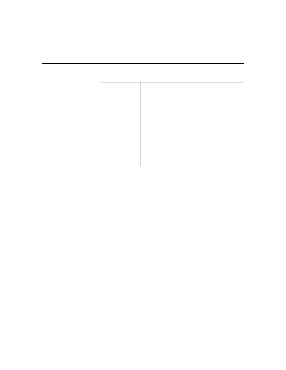
2. Make entries in the following fields:
3. Select Tune Gains. The proportional, velocity, and integral gains are
entered in the Gains dialog box.
4. Select Tune Dynamics. The maximum speed, acceleration, and
deceleration and the error tolerance are entered in the Dynamics
dialog box.
5. Select Tune Fgain. The feedforward gain is calculated and entered in
the Gains dialog box.
6. Select Follow Error Test. The following error test measures the
position error at three critical points during a trapezoidal profile move
at maximum velocity and maximum acceleration and deceleration.
Position error while the axis is moving is called following error. At
the end of the move the axis will move back to the starting point and
the three error values will be displayed. Ideally, all three of the error
values should be close to zero. Unfortunately, there are trade-offs that
must be carefully weighed to achieve optimal system performance.
Defining Gains
The Defining Gains page is for:
Field
Description
Test Increment
Type the distance for the test.
Note:
The recommended distance is ¼ of an
encoder revolution.
Tuning Travel
Limit
Type the number of units that provides a safe
travel distance given the practical travel limits
of your application.
Note:
The greater the distance, the better for
tuning.
Tuning Speed
Type the speed that the axis reach during
tuning.