Outbound link load balancing configuration example, Network requirements, Configuration considerations – H3C Technologies H3C SecPath F1000-E User Manual
Page 911: Configuration procedure
46
Outbound Link Load Balancing Configuration Example
Network requirements
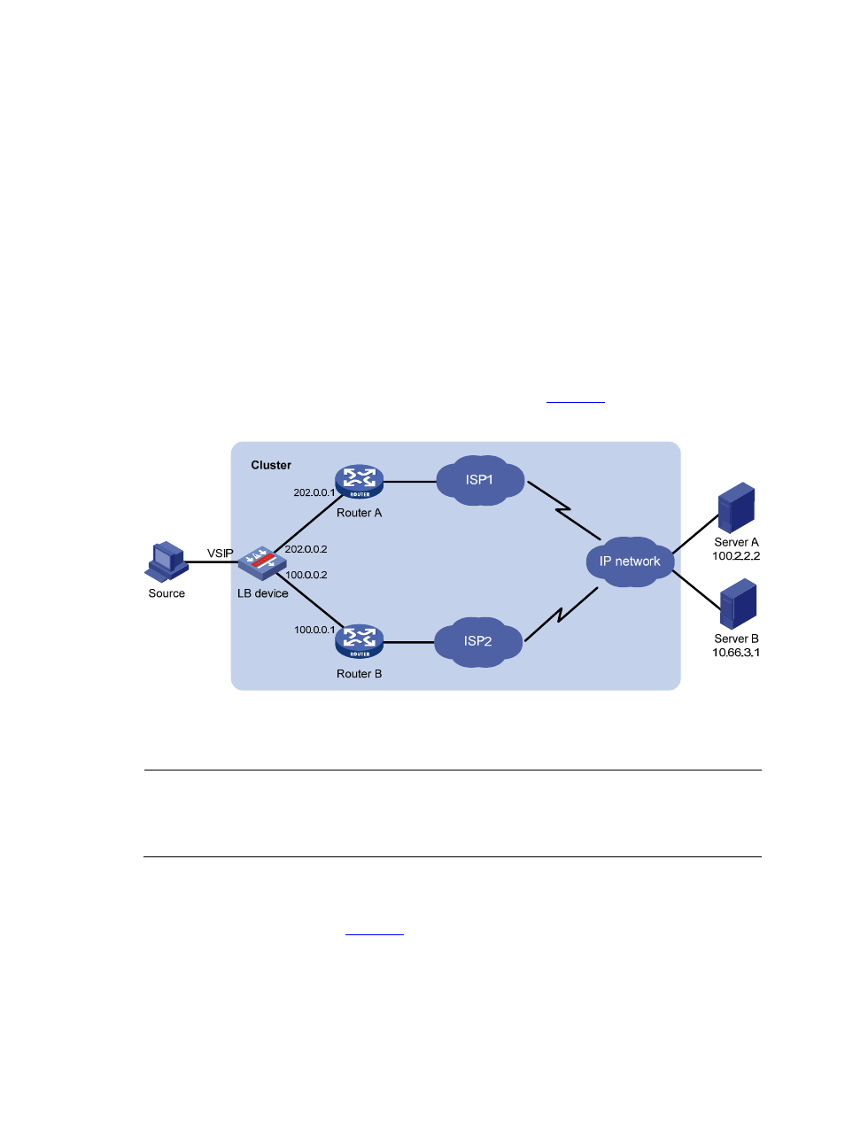
A user has rent two physical links ISP1 and ISP2 from a carrier. The router hops, bandwidth and cost of
the two links are the same, but the network delay of ISP2 is smaller than that of ISP1. It is hoped that
packets destined to the IP address in the 10.66.3.0/24 segment are transmitted on ISP1, and packets
destined to other addresses use the optimal link between the two links.
Configuration considerations
•
Outbound link load balancing is required.
•
Packets are transmitted to the destination over the best link: Best performing link detection is
adopted.
•
Packets with the destination in the 10.66.3.0/24 segment are transmitted on physical link ISP1: ACL
is adopted.
Based on the above analysis, the networking scheme as shown in
is adopted.
Figure 49 Outbound link load balancing
Configuration procedure
NOTE:
Suppose ISP1 and ISP2 have been deployed successfully and their status is healthy, and other features
such as the IP addresses of the interfaces, the zone to which the interfaces belong, and routing of the LB
device have been configured. The following describes the configuration of outbound link load balancing.
# Create ACL 3000, allowing packets with the destination 10.66.3.0/24.
•
Select Firewall > ACL from the navigation tree and then click Add to perform the following
configurations, as shown in
.