Creating a physical link, Figure 26 – H3C Technologies H3C SecPath F1000-E User Manual
Page 892
27
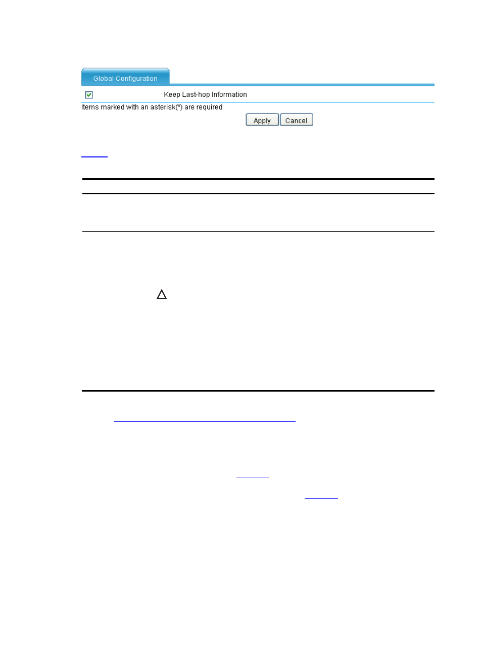
Figure 26 Global configuration
describes the configuration items for configuring global parameters.
Table 9 Global parameters configuration items
Item Description
Keep Last-hop
Information
Set whether to enable the saving last hop information function.
Enabling of this function can ensure that response packets can be returned on the original
path. This function must be enabled on level 2 LB devices in firewall load balancing.
Enable
unidirectional
traffic detection
Set whether to enable unidirectional traffic detection.
A unidirectional traffic indicates that only packets in one direction pass the device for one
session. In this case, the state machine of the device cannot process the packets. After
unidirectional traffic detection is enabled, a special state machine will be used to process
both bidirectional and unidirectional traffic.
CAUTION:
z
With unidirectional traffic detection enabled, some service functions will not be
supported (for example, ACPF will not support first TCP packet check of non SYN
packets), and the system will become less secure. Therefore, decide whether to
enable unidirectional traffic detection according to your network environments. If
unidirectional traffic exists in the network, enable the function; otherwise
unidirectional traffic cannot be processed correctly; if no unidirectional traffic exists
in the network, disable the function to avoid affecting the system security.
z
To implement DR mode server load balancing , you must enable unidirectional
traffic detection on the page displayed by selecting Firewall > Session Table >
Configuration on the LB device. For more information, see Session Management.
Outbound link load balancing configuration task list
.
Creating a Physical Link
Select High Reliability > Load Balance > Link Load Balance > Physical Link from the
navigation tree to enter the page as shown in
. The page displays the configuration information
of a physical link and the status and outgoing interface of the physical link when it is available. Click
Add to enter the page for creating a physical link, as shown in
.