Dr-mode server load balancing – H3C Technologies H3C SecPath F1000-E User Manual
Page 869
4
DR-mode server load balancing
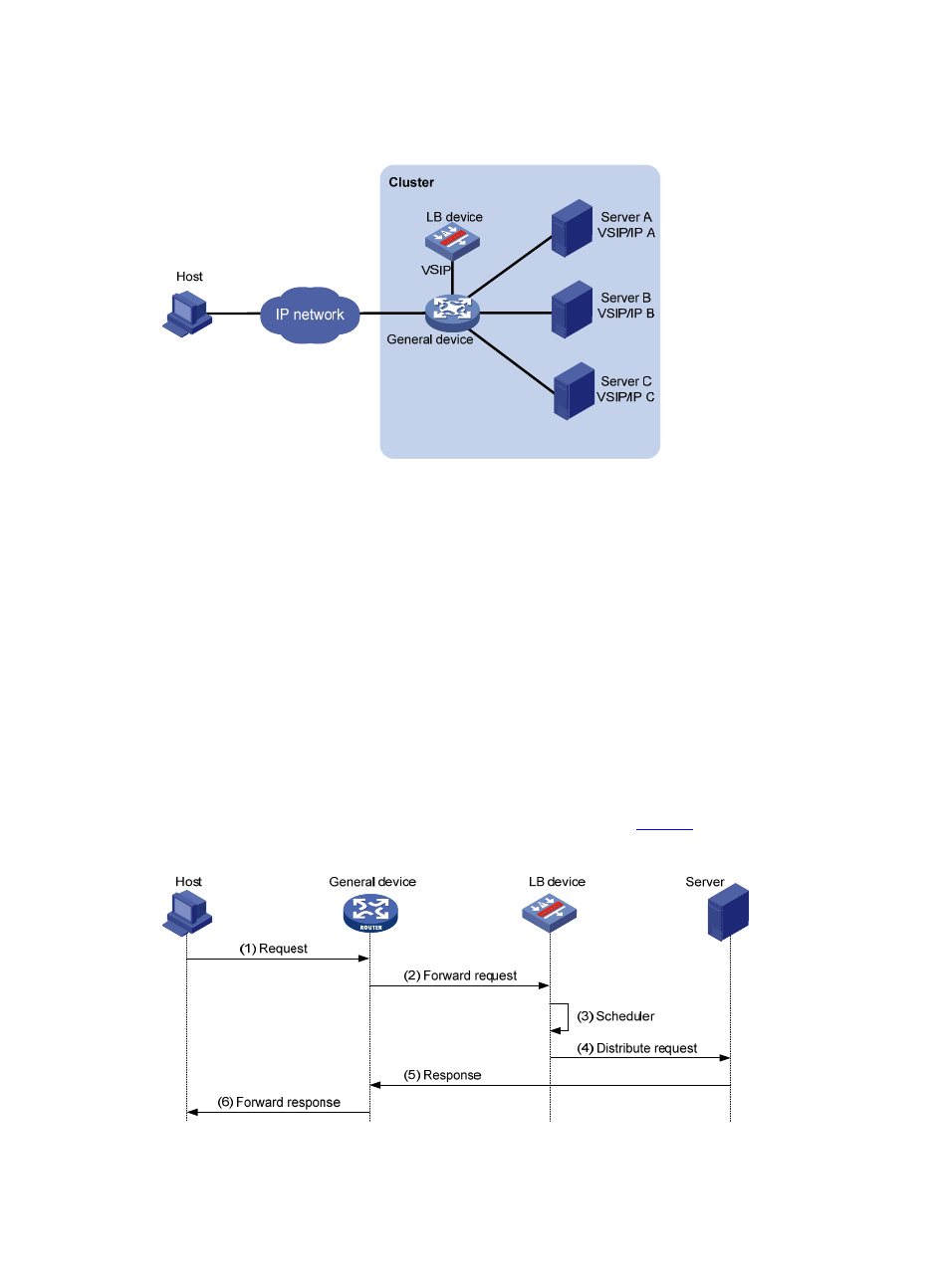
Figure 3 Network diagram for DR-mode Layer 4 server load balancing
DR mode is different from NAT mode in that NAT is not used in load balancing. This means that besides
its local IP address, a server must have the VSIP configured.
DR-mode Layer 4 server load balancing includes the following basic elements:
•
Cluster: A cluster consists of an LB device, a general device and multiple servers to provide specific
services.
•
LB device: A device that distributes different service requests to multiple servers.
•
General device: A device that forwards data according to general forwarding rules.
•
Server: A server that responds to and processes different service requests.
•
VSIP: Virtual service IP address of the cluster, used for users to request services. Besides configuring
the VSIP on the LB device, you need to configure it on servers (Because the VSIP on the server cannot
be contained in an ARP request and response, you can configure the VSIP on a loopback interface).
•
Server IP: IP address of a server, used by the LB device to distribute requests.
The work flow of DR-mode Layer 4 server load balancing is shown in
.
Figure 4 Work flow of DR-mode server load balancing
The following describes the work flow of DR-mode Layer 4 server load balancing: