H3C Technologies H3C SecPath F1000-E User Manual
Page 871
6
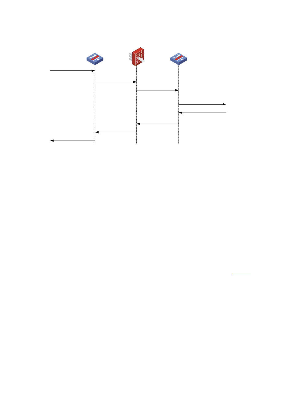
Figure 6 Work flow of firewall load balancing
(1) Traffic from source
LB device A
Firewall
(3) Forward
LB device B
(2)
Scheduler & Forward
(4) Record &
Forward to destination
(5) Traffic from destination
(7) Forward
(8) Forward to source
(6) Forward
The following describes the work flow of firewall load balancing:
1.
LB device A receives the traffic from the source.
2.
LB device A forwards the traffic to a firewall based on the destination IP address range and the
pre-configured load balancing rules of the traffic.
3.
The firewall forwards the traffic to LB device B.
4.
8As a level 2 LB device, LB device B records the firewall that forwards the traffic and then forwards
the traffic to the destination.
5.
8LB device B receives the traffic sent from the destination.
6.
8LB device B forwards the traffic to the firewall recorded in step 4.
7.
The firewall forwards the traffic to LB device A.
8.
LB device A forwards the traffic back to the source.
The load balanced firewalls between two LB devices perform network traffic load balancing, and thus
network performance is increased. This load balancing mode has another name: sandwich load
balancing.
Firewall load balancing can be used together with server load balancing, as shown in
.