3 security key setup, Atmega128rfa1 – Rainbow Electronics ATmega128RFA1 User Manual
Page 93
93
8266A-MCU Wireless-12/09
ATmega128RFA1
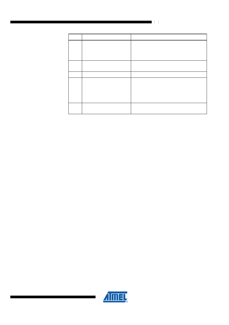
Step
Description
Description
2
AES configuration
Select AES mode: ECB or CBC
Select encryption or decryption
Enable the AES Encryption Ready Interrupt
AES_READY
3
Write Data
Write plaintext or cipher text to DATA buffer
(16 consecutive byte writes to AES_STATE)
4
Start operation
Start AES operation
5
Wait for AES finished:
1. AES_READY IRQ or
2. polling AES_DONE bit
(register AES_STATUS) or
3. wait for 24 µs
Wait until AES encryption/decryption is
finished successfully
6
Read Data
Read cipher text or plaintext from DATA buffer
(16 consecutive byte reads from AES_STATE)
Before starting any security operation a 16 Byte key must be written to the security
engine (refer to section
). This can be done by 16
consecutive write accesses to the I/O register AES_KEY. An internal address counter is
incremented automatically with every read/ write operation. An AES encryption/
decryption run resets the internal byte counter. If the key and data buffer has not been
read or written completely (all 16 Bytes), the following encryption/ decryption operation
will finish with an error.
The following step selects either Electronic Code Book (ECB) or Cipher Block Chaining
(CBC) as the AES_MODE. These modes are explained in more detail in section
"Security Operation Modes" on page 94
. Encryption or decryption must be further
selected with bit AES_DIR of register AES_CTRL.
If the AES Error or AES Ready IRQ is used, the interrupt must be enabled with bit
AES_IM.
Next the 128-bit plain text or cipher text data has to be provided to the AES hardware
engine. The 16 data bytes must be consecutively written to the AES_STATE register.
The AES_STATE register can be accessed in the same way as the key register (refer to
).
The encryption or decryption is initiated with bit AES_REQUEST = 1.
The operation takes 24 µs and the completed encryption/ decryption is indicated by the
AES_READY IRQ and the AES_DONE bit. The internal byte counter of the key and
data buffer is cleared and the resulting data can be read out.
For additional information about the key and data buffer please refer to section
"AES_KEY – AES Encryption and Decryption Key Buffer Register" on page 102
and
"AES_STATE – AES Plain and Cipher Text Buffer Register" on page 102.
Notes: 1. Access to the security block is not possible while the radio transceiver is in state
SLEEP.
2. All configurations of the security module, the SRAM content and keys are reset
during SLEEP or RESET states.
9.8.8.3 Security Key Setup
The key is stored in a 16 Byte sequential buffer. To read or write the contents of the
buffer, 16 consecutive read or write operations to the AES_KEY register are required.