2 spl - stack pointer low, 3 rampz - extended z-pointer register for elpm/spm, Atmega128rfa1 – Rainbow Electronics ATmega128RFA1 User Manual
Page 14
14
8266A-MCU Wireless-12/09
ATmega128RFA1
7.6.2 SPL – Stack Pointer Low
Bit
7
6
5
4
3
2
1
0
$3D ($5D)
SP7
SP6
SP5
SP4
SP3
SP2
SP1
SP0
SPL
Read/Write
RW
RW
RW
RW
RW
RW
RW
RW
Initial Value
1
1
1
1
1
1
1
1
The AVR Stack Pointer is implemented as two 8-bit registers SPL and SPH in the I/O
space. The number of bits actually used is implementation dependent. Note that the
data space in some implementations of the AVR architecture is so small that only SPL
is needed. In this case, the SPH Register will not be present.
•
Bit 7:0 – SP7:0 - Stack Pointer Low Byte
7.6.3 RAMPZ – Extended Z-pointer Register for ELPM/SPM
Bit
7
6
5
4
3
2
1
0
$3B ($5B)
Res5
Res4
Res3
Res2
Res1
Res0
RAMPZ1 RAMPZ0
RAMPZ
Read/Write
RW
RW
RW
RW
RW
RW
RW
RW
Initial Value
0
0
0
0
0
0
0
0
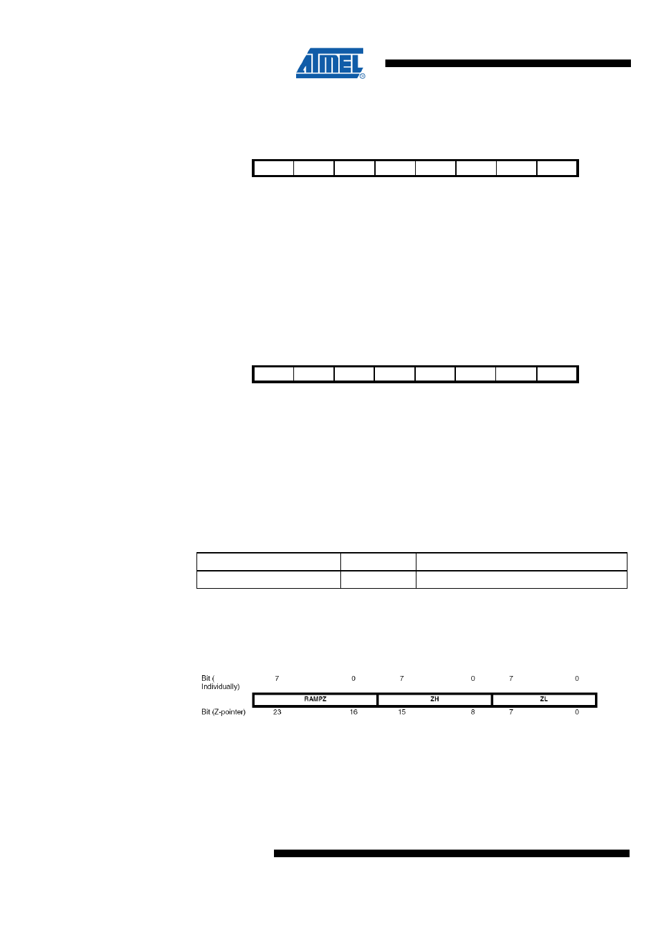
For ELPM/SPM instructions, the Z-pointer is a concatenation of RAMPZ, ZH, and ZL.
Note that LPM is not affected by the RAMPZ setting.
•
Bit 7:2 – Res5:0 - Reserved
For compatibility with future devices, be sure to write these bits to zero.
•
Bit 1:0 – RAMPZ1:0 - Extended Z-Pointer Value
These two bits represent the MSB's of the Z-Pointer.
Table 7-2 RAMPZ Register Bits
Register Bits
Value
Description
RAMPZ1:0
0
Default value of Z-pointer MSB's.
For ELPM/SPM instructions, the Z-pointer is a concatenation of RAMPZ, ZH, and ZL,
as shown in
. Note that LPM is not affected by the RAMPZ setting.
Figure 7-3. The Z-pointer used by ELPM and SPM
The actual number of bits is implementation dependent. Unused bits in an
implementation will always read as zero. For compatibility with future devices, be sure
to write these bits to zero.