4 basic operating mode timing, 1 wake-up procedure, Figure 9-13 on – Rainbow Electronics ATmega128RFA1 User Manual
Page 39: Atmega128rfa1
39
8266A-MCU Wireless-12/09
ATmega128RFA1
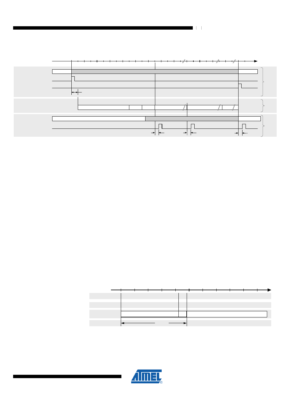
Figure 9-13. Timing of TRX24_RX_START, TRX24_XAH_AMI, TRX24_TX_END and TRX24_RX_END Interrupts in
Basic Operating Mode
1 2 8
1 6 0
1 9 2
0
1 9 2 + ( 9 + m ) * 3 2
- 1 6
T i m e [ µ s ]
R
X
(D
e
v
ic
e
2
)
T R X 2 4 _ R X _ S T A R T
t
I R Q
R X _ O N
R X _ O N
I R Q
T R X _ S T A T E
I n t e r r u p t l a t e n c y
T R X 2 4 _
R X _ E N D
T R X 2 4 _ X A H _ A M I
t
I R Q
t
I R Q
B U S Y _ R X
T R X 2 4 _ T X _ E N D
T
X
(D
e
v
ic
e
1
)
P L L _ O N
B U S Y _ T X
P L L _ O N
I R Q
S L P T R
T R X _ S T A T E
T y p . P r o c e s s i n g D e l a y
1 6 µ s
F
ra
m
e
o
n
A
ir
P r e a m b l e
S F D
P H R
M S D U
4
1
1
m
N u m b e r o f O c t e t s
F r a m e C o n t e n t
M H R
7
F C S
2
9.4.1.4 Basic Operating Mode Timing
The following paragraphs depict state transitions and their timing properties. Timing
figures are explained in
9.4.1.4.1 Wake-up Procedure
The wake-up procedure from radio transceiver SLEEP state is shown in
. This figure implies, that the microcontroller is already running and hence, the
digital voltage regulator is enabled. If the microcontroller clock source is set to
Transceiver Clock, the crystal oscillator is also running, which reduces the radio
transceiver wake-up time further. For information about the wake-up timing of the
microcontroller, depending on the different clock source options, refer to
and Clock Options" on page 147
.
In order to calculate the total wake-up delay from microcontroller sleep mode (see
"Power Management and Sleep Modes" on page 156
), the microcontroller wake-up
time, including the voltage regulator ramp-up and the radio transceiver wake-up time
has to be added.
Figure 9-14. Wake-up Procedure from Transceiver SLEEP State
0
Event
State
Block
100
400
Time [µs]
Tim e
t
TR2
TRX_O FF
TRX24_AW AKE IRQ
SLPTR = 0
SLEEP
200
XO SC startup
XO SC enabled
FTN
The radio transceiver SLEEP state is left by releasing bit SLPTR to “0”. This restarts the
XOSC if it is not already running. After t
TR2
= 215 µs + 25 µs = 240 µs (see
page 42) the radio transceiver enters TRX_OFF state. If the XOSC is already running,
the radio transceiver enters TRX_OFF state after 25 µs.