7 transceiver crystal oscillator, Figure 11-2 on, Atmega128rfa1 – Rainbow Electronics ATmega128RFA1 User Manual
Page 151
151
8266A-MCU Wireless-12/09
ATmega128RFA1
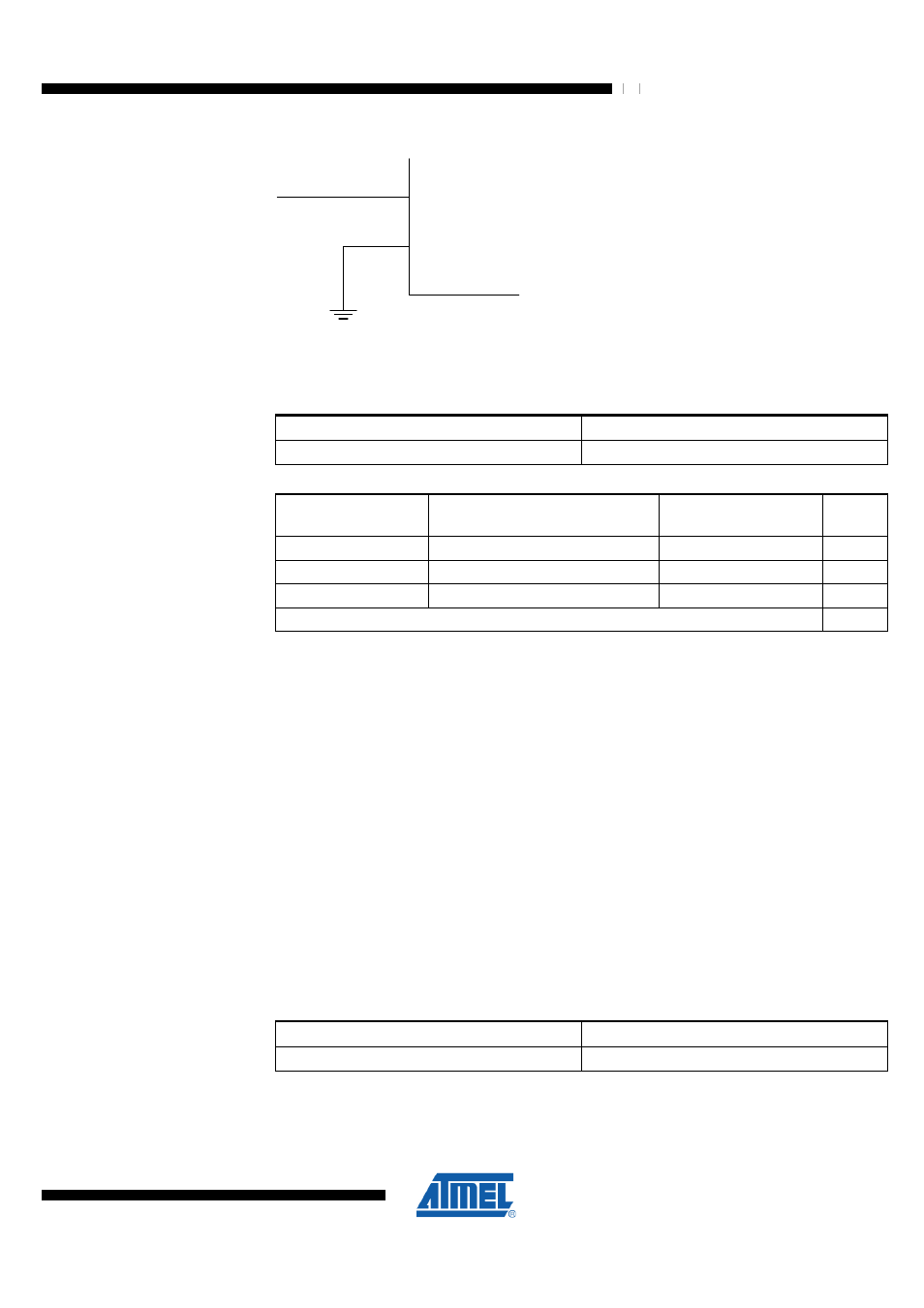
Figure 11-2. External Clock Drive Configuration
CLKI
VSS
external clock
When this clock source is selected, start-up times are determined by the SUT Fuses as
shown in
Table 11-7. External Clock Frequency
Nominal Frequency
CKSEL3:0
0 – 16 MHz
0000
Table 11-8. Start-up Times for the External Clock Selection
Power Conditions
Start-up Time from Power-down
and Power-save
Additional Delay from
Reset
SUT1:0
BOD enabled
6 CK
14 CK
00
Fast rising power
6 CK
14 CK + 4.0 ms
01
Slowly rising power
6 CK
14 CK + 64 ms
10
Reserved
11
When applying an external clock, it is required to avoid sudden changes in the applied
clock frequency to ensure stable operation of the microcontroller unit (MCU). A variation
in frequency of more than 2% from one clock cycle to the next can lead to unpredictable
behavior. If changes of more than 2% are required, ensure that the MCU is kept in
Reset during the changes.
Note that the System Clock Prescaler can be used to implement run-time changes of
the internal clock frequency while still ensuring stable operation. Refer to section
"System Clock Prescaler" on page 152
for details.
11.7 Transceiver Crystal Oscillator
The integrated crystal oscillator for the radio transceiver generates a low-jitter 16MHz
clock frequency. See section
"Crystal Oscillator (XOSC)" on page 80
for details about
the operation of this oscillator. The AVR core and the radio transceiver operate
synchronously on the same clock if this oscillator is selected. If the transceiver crystal
oscillator is selected as AVR core clock, it remains enabled even if the radio transceiver
is in SLEEP mode or its power reduction bit PRTRX24 is set.
Table 11-9. Transceiver Crystal Clock Operating Mode
Frequency Range (MHz)
CKSEL3:0
(1)
16
1111 - 0110
Notes:
1. All CKSEL fuse values have the same significance.