Atmega128rfa1 – Rainbow Electronics ATmega128RFA1 User Manual
Page 109
109
8266A-MCU Wireless-12/09
ATmega128RFA1
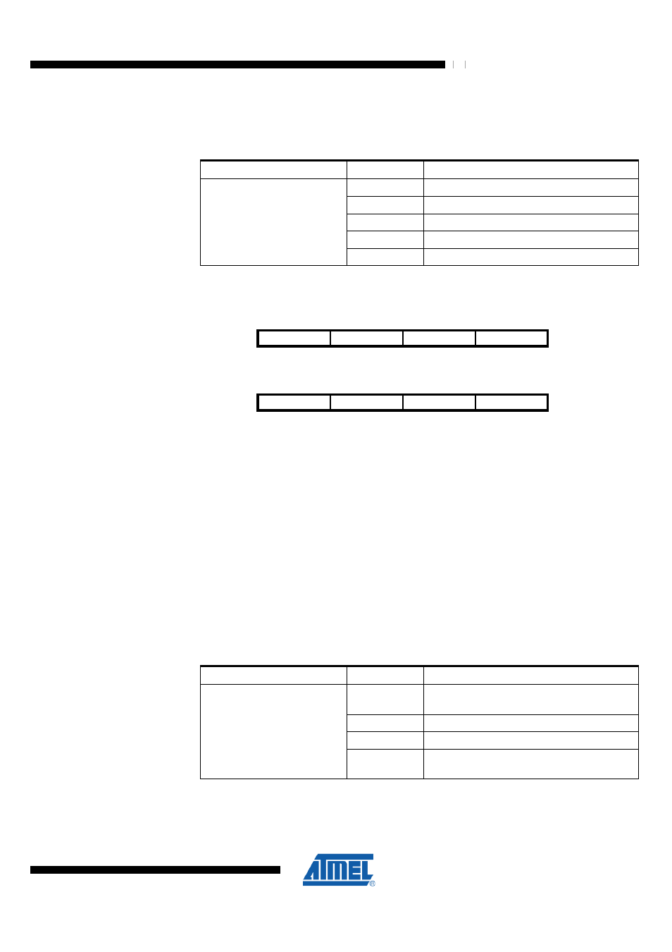
µs. For manually initiated ED measurements in these modes the measurement period is
still 128 µs as long as the receiver is in RX_ON state. A value other than 0xFF indicates
the result of the last ED measurement.
Table 9-41 ED_LEVEL Register Bits
Register Bits
Value
Description
0x00
Minimum result of last ED measurement
0x01
P(RF) = RSSI_BASE_VAL+ED [dBm]
0x02
...
0x54
Maximum result of last ED measurement
ED_LEVEL7:0
0xFF
Reset value
9.12.12 PHY_CC_CCA – Transceiver Clear Channel Assessment (CCA) Control Register
Bit
7
6
5
4
NA ($148)
CCA_REQUEST
CCA_MODE1
CCA_MODE0
CHANNEL4
PHY_CC_CCA
Read/Write
RW
RW
RW
RW
Initial Value
0
0
1
0
Bit
3
2
1
0
NA ($148)
CHANNEL3
CHANNEL2
CHANNEL1
CHANNEL0
PHY_CC_CCA
Read/Write
RW
RW
RW
RW
Initial Value
1
0
1
1
This register is provided to initiate and control a CCA measurement.
•
Bit 7 – CCA_REQUEST - Manual CCA Measurement Request
A manual CCA measurement is initiated with setting CCA_REQUEST=1. The end of
the CCA measurement is indicated by the TRX24_CCA_ED_DONE interrupt. Register
bits CCA_DONE and CCA_STATUS of register TRX_STATUS are updated after a
CCA_REQUEST. The register bit is automatically cleared after requesting a CCA
measurement with CCA_REQUEST=1.
•
Bit 6:5 – CCA_MODE1:0 - Select CCA Measurement Mode
The CCA mode can be selected using these register bits. Note that IEEE 802.15.4-
2006 CCA Mode 3 defines the logical combination of CCA Mode 1 and 2 with the
logical operators AND or OR. This can be selected with CCA_MODE=0 for logical
operation OR and CCA_MODE=3 for logical operation AND.
Table 9-42 CCA_MODE Register Bits
Register Bits
Value
Description
0
Mode 3a, Carrier sense OR energy above
threshold
1
Mode 1, Energy above threshold
2
Mode 2, Carrier sense only
CCA_MODE1:0
3
Mode 3b, Carrier sense AND energy above
threshold
•
Bit 4:0 – CHANNEL4:0 - RX/TX Channel Selection
These register bits define the RX/TX channel. The channel assignment is according to
IEEE 802.15.4.