3 scanning the rston pin, 6 boundary-scan related register in i/o memory, 1 mcucr - mcu control register – Rainbow Electronics ATmega128RFA1 User Manual
Page 447: 2 mcusr - mcu status register, Atmega128rfa1
447
8266A-MCU Wireless-12/09
ATmega128RFA1
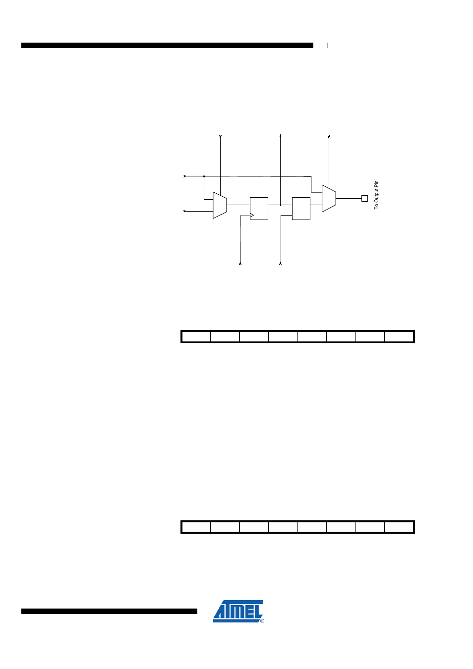
29.5.3 Scanning the RSTON Pin
For the low-active reset output pin RSTON a boundary-scan cell as shown in
is inserted.
Figure 29-6. Boundary-scan Cell for Output Pins without Pull-up Function
0
1
0
1
EXTEST
To Next Cell
ShiftDR
From System Logic
From Previous
Cell
UpdateDR
ClockDR
LD0
FF0
D
Q
D
Q
G
29.6 Boundary-scan Related Register in I/O Memory
29.6.1 MCUCR – MCU Control Register
Bit
7
6
5
4
3
2
1
0
$35 ($55)
JTD
MCUCR
Read/Write
RW
Initial Value
0
The MCU Control Register contains control bits for general Microcontroller Unit
functions.
•
Bit 7 – JTD - JTAG Interface Disable
When this bit is zero, the JTAG interface is enabled if the JTAGEN Fuse is
programmed. If this bit is one, the JTAG interface is disabled. In order to avoid
unintentional disabling or enabling of the JTAG interface, a timed sequence must be
followed when changing this bit: The application software must write this bit to the
desired value twice within four cycles to change its value. Note that this bit must not be
altered when using the On-chip Debug system.
29.6.2 MCUSR – MCU Status Register
Bit
7
6
5
4
3
2
1
0
$34 ($54)
JTRF
MCUSR
Read/Write
RW
Initial Value
0
The MCU Status Register provides information on which reset source caused an MCU
reset.