3 high data rate frame buffer access, 4 high data rate energy detection, Figure 9-30 on – Rainbow Electronics ATmega128RFA1 User Manual
Page 87: Atmega128rfa1
87
8266A-MCU Wireless-12/09
ATmega128RFA1
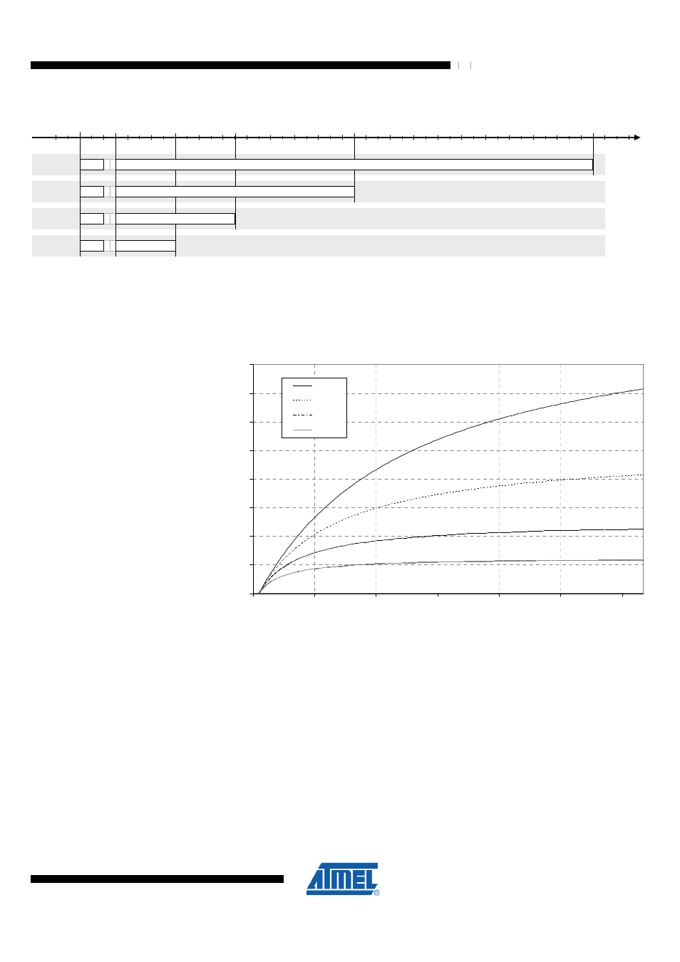
Figure 9-30. High Data Rate Frame Structure
250 kb/s
0
time [µs]
192
S
F
D
P
H
R
832
1472
2752
500 kb/s
S
F
D
P
H
R
1000 kb/s
S
F
D
P
H
R
2000 kb/s
S
F
D
P
H
R
512
F
C
S
F
C
S
PSDU: 80 octets
PSDU: 80 octets
PSDU: 80 octets
PSDU: 80 octets
The effective data rate is smaller than the selected data rate due to the overhead
caused by the SHR, the PHR and the FCS. The overhead depends further on the
length of the PSDU. A graphical representation of the effective data rate is shown in the
following figure:
Figure 9-31. Effective Data Rate “B” for High Data Rate Mode
0
200
400
600
800
1000
1200
1400
1600
0
20
40
60
80
100
120
PSDU length in octets
B
[
k
b
p
s
]
2000
1000
500
250
2000 kbps
1000 kbps
500 kbps
250 kbps
Therefore High Data Rate transmission and reception is useful for large PSDU lengths
due to the higher effective data rate or to reduce the power consumption of the system.
Furthermore the active on-air time using High Data Rate Modes is significantly reduced.
9.8.2.3 High Data Rate Frame Buffer Access
The Frame Buffer access to read or write frames for High Data Rate communication is
similar to the procedure described in
. However the last byte
in the Frame Buffer after the PSDU data is the ED value rather than the LQI value.
9.8.2.4 High Data Rate Energy Detection
According to IEEE 802.15.4 the ED measurement duration is 8 symbol periods. For
frames operated at higher data rates the automated ED measurement duration is
reduced to 32 µs to take the reduced frame length into account (
).